LNG vaporization

a technology of liquid vaporization and lng, which is applied in the direction of fluid heaters, container discharge methods, lighting and heating apparatus, etc., can solve the problems of lng vaporizers currently in use, the widespread use of lng as fuel source, and the limitations of natural gas in such applications, so as to increase the heat produced by an internal combustion engine

Inactive Publication Date: 2015-05-21
SHAABAN KHALED +1
View PDF14 Cites 33 Cited by
  • Summary
  • Abstract
  • Description
  • Claims
  • Application Information

AI Technical Summary

Benefits of technology

[0014]In another aspect, the present invention provides a method of vaporizing LNG comprising the steps of increasing the heat produced by an internal combustion engine by artificially loading the internal combustion engine by using the internal combustion engine to drive hydraulic pump(s) and forcing the hydraulic pump-pressurized discharge fluid flow through a restricted orifice thus forcing the engine to burn ...

Problems solved by technology

Despite the cost savings and significantly decreased emissions, there are barriers to the widespread use of natural gas in such applications as the oilfield.
However, the technology of the LNG vaporizers currently in use is an obstacle that prevents widespread use of LNG as a fuel source in such applications as the oilfield in which large volumes of natural gas are required to meet on-site energy needs.
The heat exchangers of such vaporizers require a large surface area to extract sufficient ambient heat for vaporizing LNG, thus requiring that the vaporizer have a large footprint, and the efficiency of such vaporizers is dependent on ambient air temperature.
Further, ice build-up on the heat exchanger surface area imposes limits on the number of hours the vaporizer can operate and overall vaporizing efficiency.
One way to overcome this ice build-up problem is to switch between multiple vaporizers, but using multiple vaporizers further increases the overall footprint of the vaporizer and limits the mobility of the vaporizer such that moving the vaporizer from on site to another may require multiple truckloads and over-the-road weight and height special permits.
This type of vaporizer is typically an integral component of an LNG transport tanker and requires an electrical source on-site, and such power sources are not always available at some sites such as hydraulic fracking locations.
Further, multiple vaporizers of this type are needed on locations requiring high LNG flow requirements such that overall footprint is large and mobility is compromised by the need for multiple truck loads to move the vaporizer(s) from site to site.
However, such vaporizers require a fired fuel source, typically a burner/boiler, that must be located at least 50-100 feet away from the LNG source, which is a limiting factor in some tight locations and could present safety concerns.
The modest pressure and rate output of these known/exist...

Method used


Image

  • LNG vaporization
  • LNG vaporization

Examples


Embodiment Construction

)

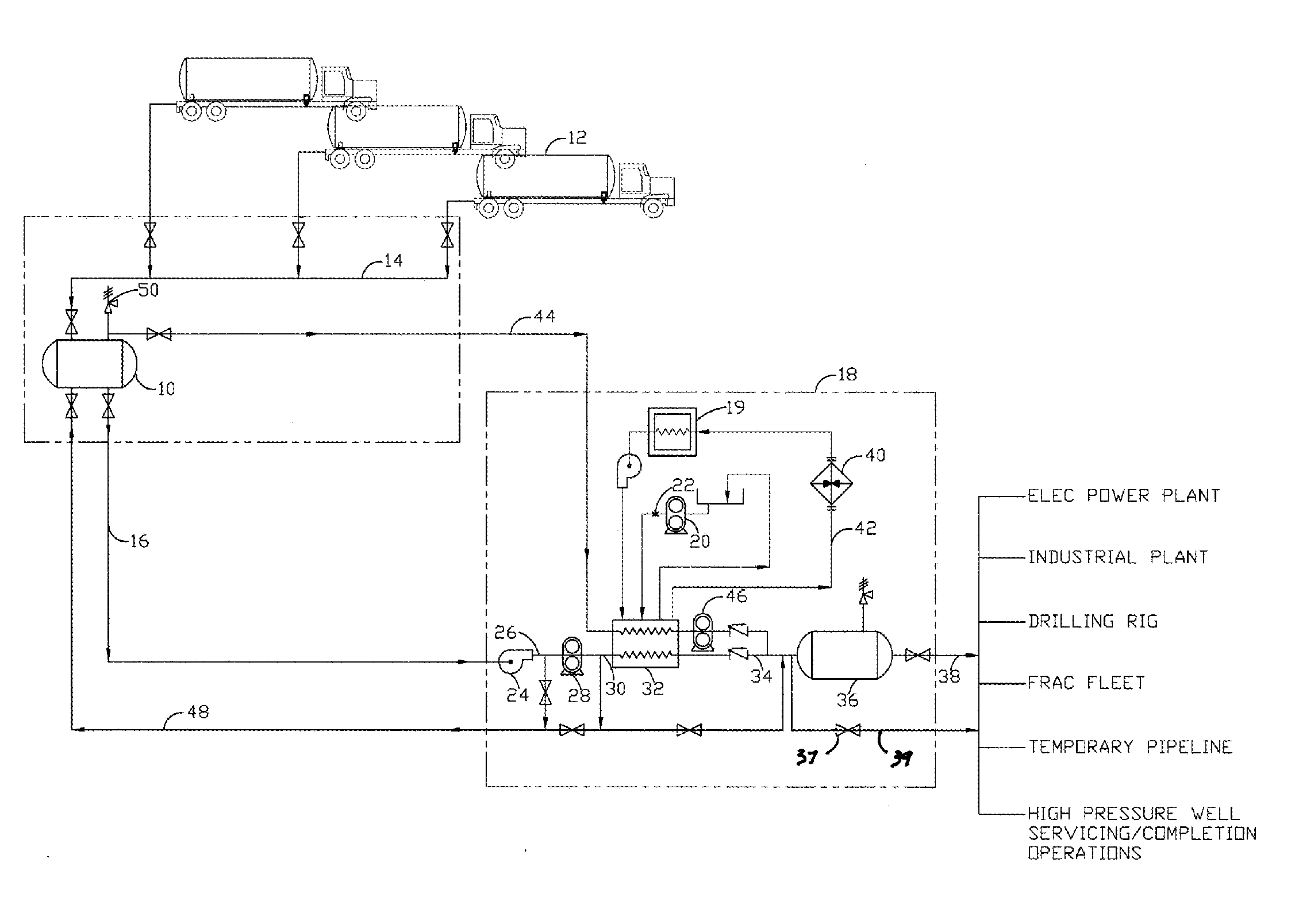
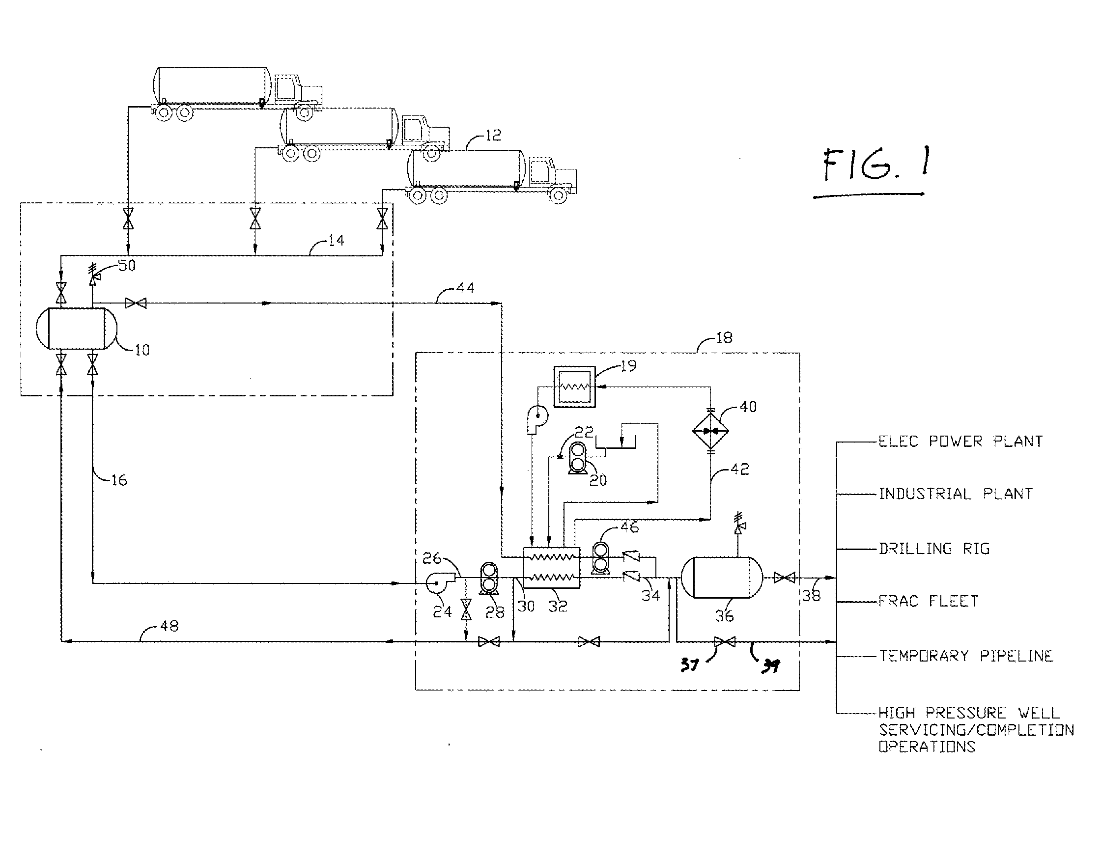
[0016]Referring to FIG. 1, LNG is provided to a storage tank 10 by one or more LNG transport trucks 12 through a loading manifold 14, all constructed in accordance with known LNG storage and handling systems. LNG is output from storage tank 10 through supply line 16 to the LNG vaporizer of the present invention, indicated generally at reference numeral 18, that is itself powered by an internal combustion engine 19 that may be diesel or natural gas powered, or that may be powered on a mix of diesel and natural gas. The internal combustion engine 19 of LNG vaporizer 18 is “artificially” loaded by driving a hydraulic pump 20 that pumps hydraulic fluid through the restricted orifice 22 of a sequencing valve, the engine 19 producing more heat that is “captured” in the engine coolant as engine 19 works harder and burn more fuel to push hydraulic fluid through valve orifice 22. In the embodiment described herein, the internal combustion engine 19 of LNG vaporizer 18 provides three heat so...


PUM


Abstract

Apparatus and methods for vaporizing LNG while producing sufficient volume of compressed natural gas at sufficient pressure to meet the needs of internal combustion engines, gas turbines, or other high consumption devices operating on natural gas or on a mixture of diesel and natural gas. The LNG vaporizer of the present invention incorporates a reciprocating pump to provide vaporized LNG to an output at rates and pressures as required by the particular application. The heat rejected into the engine coolant and the exhaust stream from an artificially loaded internal combustion engine, as well as the hydraulic heat resulting from artificially loading the engine, is transferred to the LNG as the LNG passes through a heat exchanger. Exhaust heat is transferred to the engine coolant after the coolant passes through the heat exchanger.

Description

BACKGROUND OF THE INVENTION[0001]The present invention relates to the vaporization of cryogenic liquids. In more detail, the present invention relates to mobile vaporizers and methods for vaporizing LNG in sufficient volume and pressure to enable the use of the vaporized natural gas as a fuel source or in applications in which large quantities of vaporized LNG / compressed natural gas (CNG) are needed, for instance, for internal combustion engines or gas turbines operating at high horsepower, for electrical power generation during periods of peak demand, to displace other fuels such as oil or coal as fuel for power generation, and for well servicing applications utilizing CNG.[0002]Recent increases in the cost of diesel fuel and changes in regulations governing the emissions from diesel engines have motivated the operators of diesel fleets to investigate the use of alternative fuels. The price advantage and availability of natural gas make it one of several alternative fuels currently...

Claims


Application Information

Patent Timeline
IPC IPC(8): F24H9/00
CPCF24H9/00F17C7/04F17C2201/054F17C2221/033F17C2223/0161F17C2223/033F17C2225/0123F17C2225/0161F17C2227/0142F17C2227/0302F17C2227/039F17C2227/0393F17C2265/03F17C2265/05
Inventor SHAABAN, KHALEDNGUYEN, DINH
Owner SHAABAN KHALED
Why Eureka
Try Eureka