Gas Turbine Blade

a technology of gas turbine blades and blades, which is applied in the manufacture of engines, mechanical equipment, machines/engines, etc., can solve the problems of increasing the amount of cooling air, reducing the thermal efficiency of the gas turbine as a whole, so as to reduce the temperature difference between the pressure side and the suction side, and reduce the effect of thermal stress

Active Publication Date: 2015-05-21
MITSUBISHI POWER LTD
View PDF100 Cites 7 Cited by
  • Summary
  • Abstract
  • Description
  • Claims
  • Application Information

AI Technical Summary

Benefits of technology

[0007]Typically gas turbine blades are cooled by the air extracted from a compressor; thus, increases in the amount of the cooling air reduce the thermal efficiency of the gas turbine as a whole. Also, cooling structures with high cooling efficiency tend to be high in pressure loss. Since the flow of the cooling air into the gas turbine blades is caused by the pressure difference between the extraction pressure of the compressor and the pressure within the main flow passage of the turbine, excessively high pressure losses by such cooling structures make it impossible to supply a sufficient amount of cooling air to the gas turbine blades. Thus, in order to improve the thermal efficiency of the gas turbine while maintaining the soundness of the gas turbine blades, sufficient heat exchange needs to be performed with a small amount of cooling air.
[0009]The present invention has been made in view of the above, and an object of the invention is to provide a gas turbine blade that is capable of reducing the temperature difference between the pressure side and the suction side even if the trailing-edge cooling channel is narrow, thereby lessening thermal stress as well.
[0011]In accordance with the present invention, even if the trailing-edge cooling channel is narrow, the temperature difference between the pressure side and the suction side can be reduced, and thermal stress can be lessened as well.

Problems solved by technology

Typically gas turbine blades are cooled by the air extracted from a compressor; thus, increases in the amount of the cooling air reduce the thermal efficiency of the gas turbine as a whole.
Also, cooling structures with high cooling efficiency tend to be high in pressure loss.
Since the flow of the cooling air into the gas turbine blades is caused by the pressure difference between the extraction pressure of the compressor and the pressure within the main flow passage of the turbine, excessively high pressure losses by such cooling structures make it impossible to supply a sufficient amount of cooling air to the gas turbine blades.
When the vortex generators disclosed in the above patent literature are to be applied to such a narrow cooling channel, the vortex generators need to be reduced in size, which may fail to promote cooling sufficiently.

Method used


Image

  • Gas Turbine Blade
  • Gas Turbine Blade
  • Gas Turbine Blade

Examples


Embodiment Construction

[0019]An embodiment of the present invention will now be described with reference to the accompanying drawings.

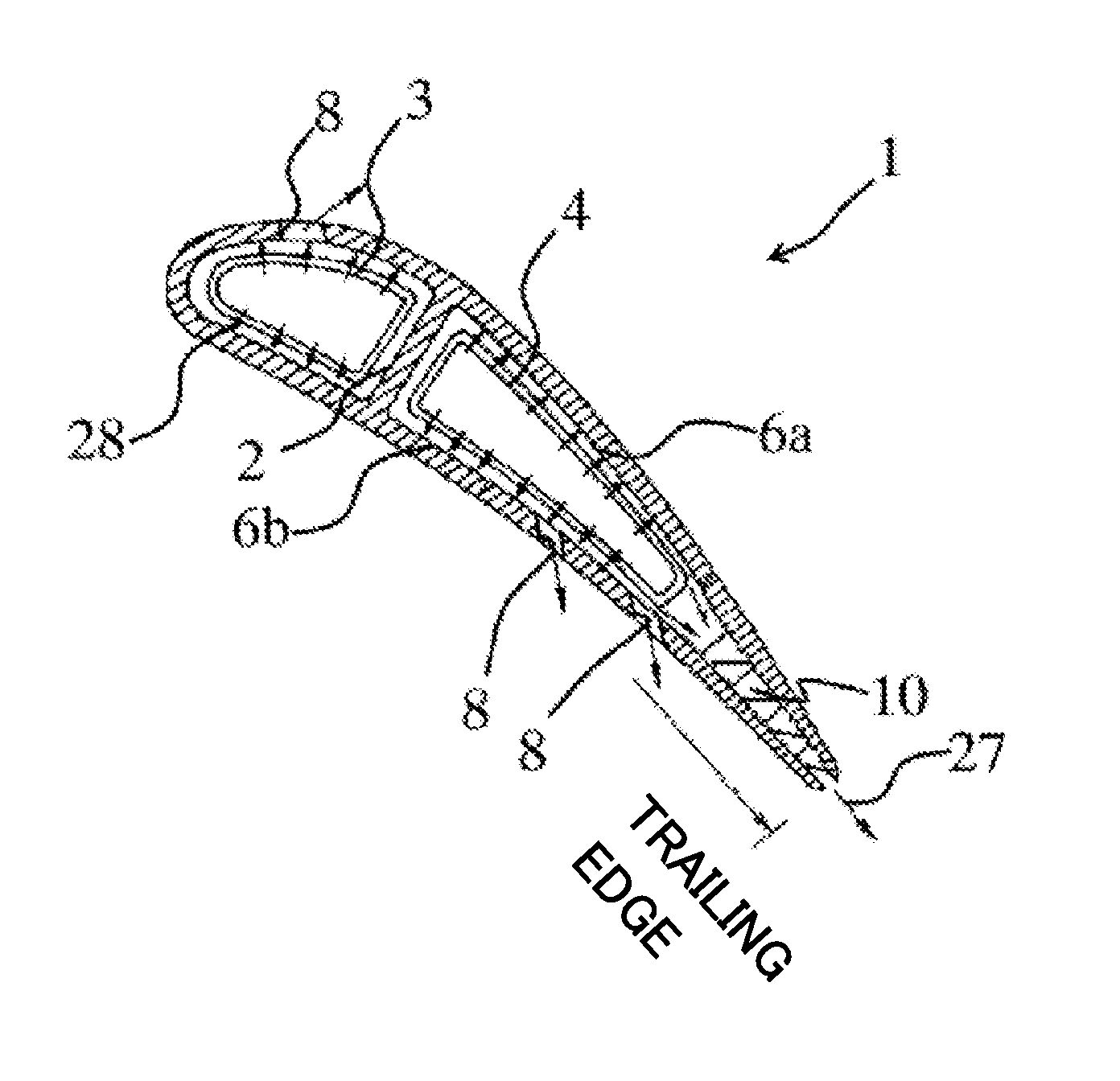
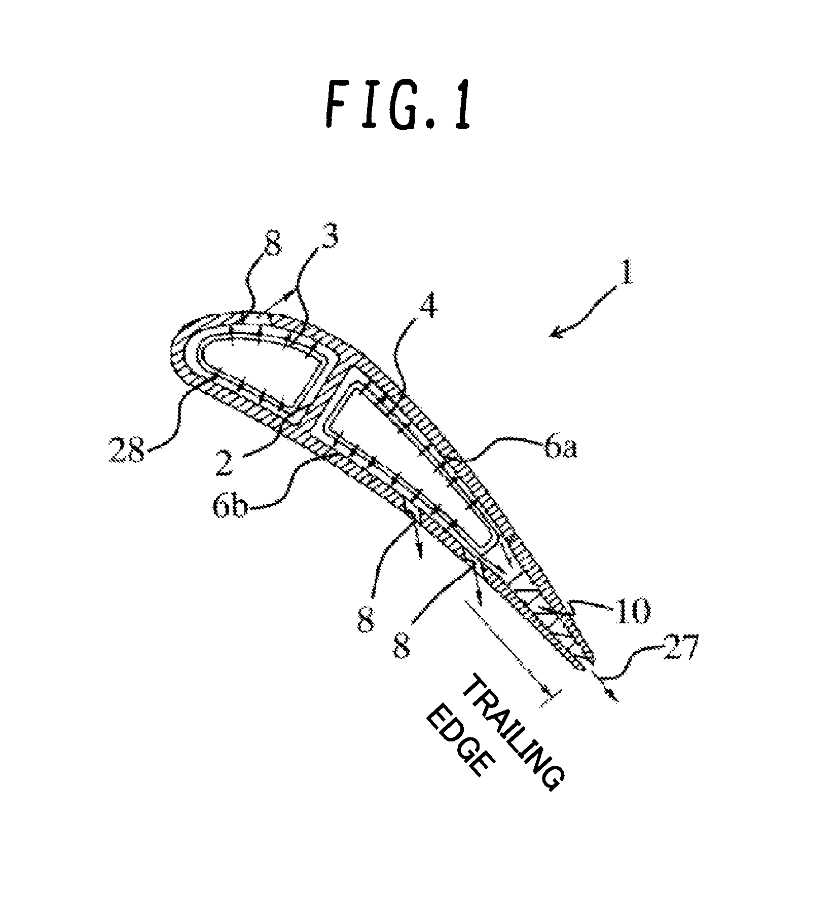
[0020]FIG. 1 is a circumferential cross section of a gas turbine blade according to an embodiment of the invention, and FIG. 2 is a radial cross section of the gas turbine blade. The circumferential cross section of FIG. 1 is obtained by cutting the blade with the side surface of a cylinder that shares the same axis as a gas turbine rotor while the radial cross section of FIG. 2 is obtained by cutting the blade with a plane that passes the rotational center of the rotor and extends in a radial direction of the rotor. FIG. 3 is an enlarged radial cross section of the trailing-edge cooling channel of the gas turbine blade, and FIG. 4 is a perspective view of the trailing-edge cooling channel.

[0021]In a gas turbine, a compressor compresses air, and a combustor combusts the air compressed by the compressor with fuel. The resultant combustion gas is directed to a turbine to obta...


PUM


Abstract

The invention provides a gas turbine blade that is capable of reducing the temperature difference between the pressure side and the suction side even if the trailing-edge cooling channel is narrow, thereby lessening thermal stress as well.A gas turbine blade 1 comprises: an internal trailing-edge cooling channel formed by a suction-side cooling target surface 6a and a pressure-side cooling target surface 6b that face each other; and multiple vortex-generator-shaped fins 10 disposed between the two cooling target surfaces 6a and 6b such that the fins 10 connect the two cooling target surfaces 6a and 6b. Each of the vortex-generator-shaped fins 10 includes an oblique surface 33 located on the downstream side of the flow direction of a cooling medium. A normal line 34 to the oblique surface 33 intersects with one of the two cooling target surfaces 6a and 6b.

Description

BACKGROUND OF THE INVENTION[0001]1. Field of the Invention[0002]The present invention relates to gas turbine blades having internal cooling structures.[0003]2. Description of the Related Art[0004]In recent years, the working gases of gas turbines are increasingly getting higher in temperature for better thermal efficiency. This requires at the same time improvements in the cooling performance of gas turbine blades. A gas turbine blade having internal cooling structures allows cooling air to flow through the interior of the blade, and the blade is cooled by heat exchange with the cooling air. At the trailing edge of the blade, however, a sufficient air channel height often cannot be secured. Thus, pin fin cooling is usually employed in the trailing-edge cooling channel, whereby pin fins are disposed between a suction-side cooling target surface and a pressure-side cooling target surface (i.e., between the inner wall surfaces of the blade). Such pin fins are also effective in increasi...

Claims


Application Information

Patent Timeline
Patent Type & Authority Applications(United States)
IPC IPC(8): F02C7/18F01D5/18
CPCF02C7/18F05D2260/221F01D5/18F01D5/187F05D2260/2212F05D2260/22141F05D2250/38F05D2250/21F01D5/189
Inventor HORIUCHI, YASUHIROTAGAWA, HISATOMORISAKI, TETSURO
Owner MITSUBISHI POWER LTD
Why Eureka
Try Eureka