Supercharge Your Innovation With Domain-Expert AI Agents!

Passivation process to prevent tiw corrosion

Active Publication Date: 2015-05-28
TEXAS INSTR INC
View PDF4 Cites 2 Cited by
  • Summary
  • Abstract
  • Description
  • Claims
  • Application Information

AI Technical Summary

Benefits of technology

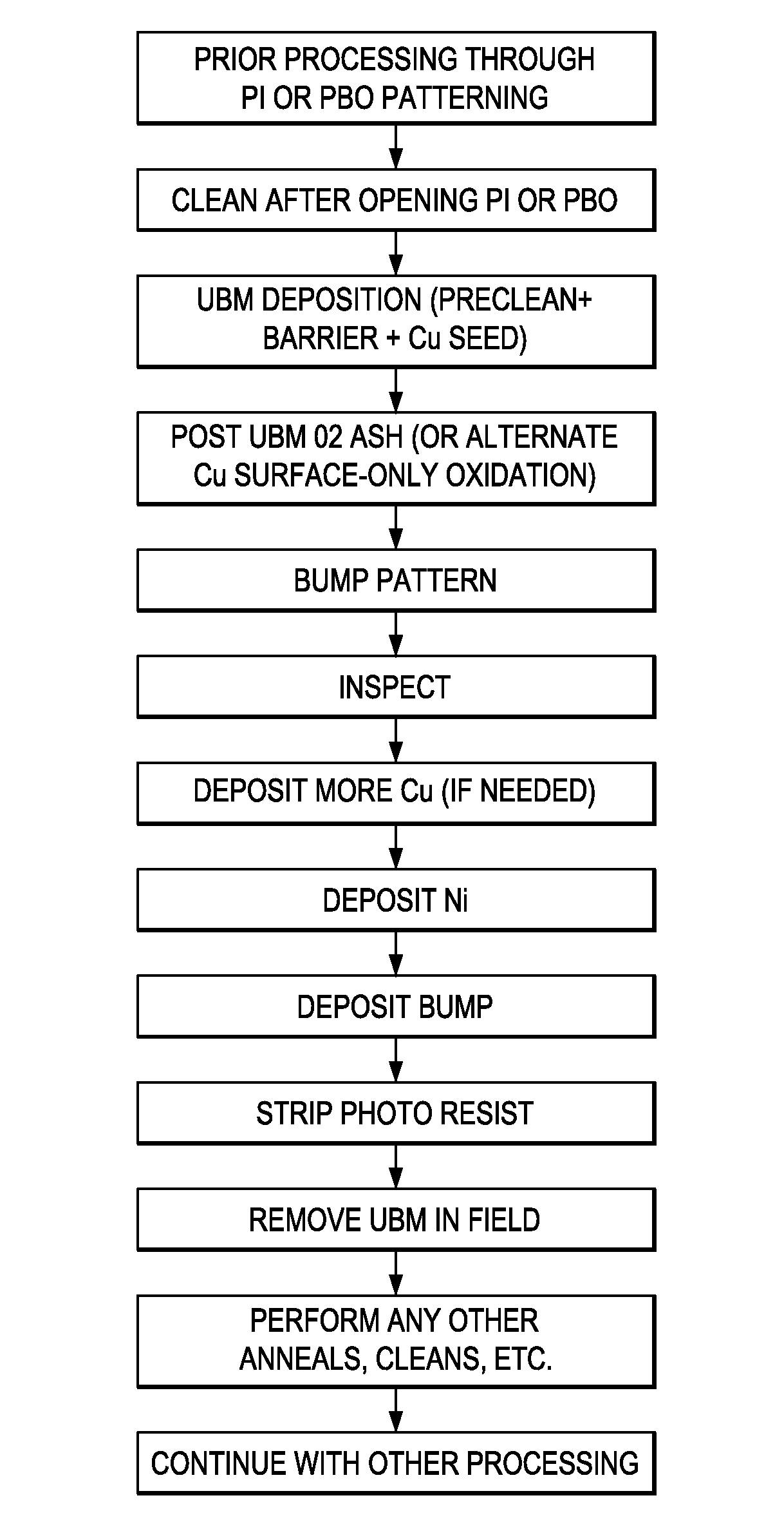
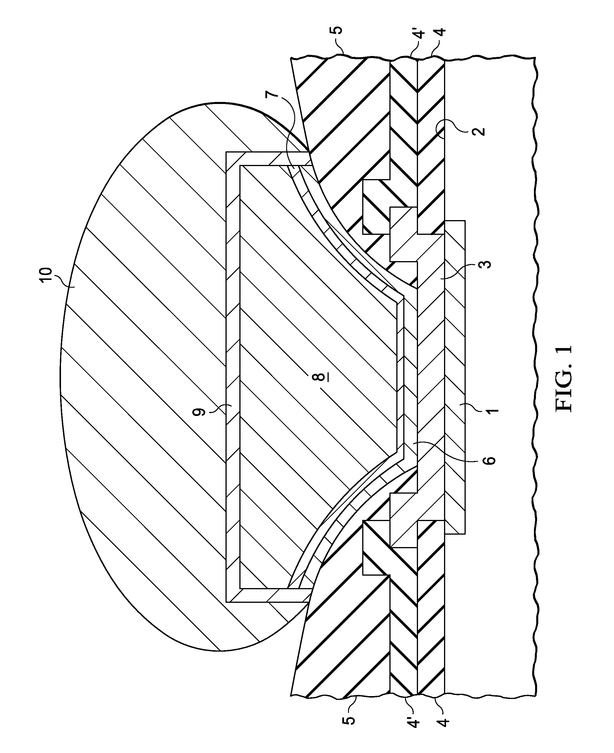
The present application provides a method for making an integrated circuit with an under bump metallization structure. The method involves forming a passivation layer, patterning it to expose a portion of the bond pad, adding a barrier layer (e.g. TiW) and a seed layer (e.g. Cu) over the passivation layer and patterning the seed layer to create a patterned surface. A metal oxide layer (e.g. CuO) is then applied to prevent corrosion of the seed layer during the bump pattern step. A bump resist pattern is created over the metal oxide layer, which is used to remove any metal oxide layer that may be exposed during the process. Finally, a metal layer (e.g. Cu) is added to the patterned surface.

Problems solved by technology

However, when the size of the chip-package interconnection scales down, the performance and reliability of wirebonding may be affected since wirebonding requires the routing of all the input / output (I / O) connections to the edges of the chip.
Since the formed intermetallic compound is brittle, the bonding strength between the solder bump and the bond pad would be greatly compromised if copper is in direct contact with the solder bump.

Method used


Image

  • Passivation process to prevent tiw corrosion
  • Passivation process to prevent tiw corrosion
  • Passivation process to prevent tiw corrosion

Examples


Embodiment Construction

[0019]The present invention is described with reference to the attached figures. The figures are not drawn to scale and they are provided merely to illustrate the invention. Several aspects of the invention are described below with reference to example applications for illustration. It should be understood that numerous specific details, relationships, and methods are set forth to provide an understanding of the invention. One skilled in the relevant art, however, will readily recognize that the invention can be practiced without one or more of the specific details or with other methods. In other instances, well-known structures or operations are not shown in detail to avoid obscuring the invention. The present invention is not limited by the illustrated ordering of acts or events, as some acts may occur in different orders and / or concurrently with other acts or events. Furthermore, not all illustrated acts or events are required to implement a methodology in accordance with the pre...


PUM


Abstract

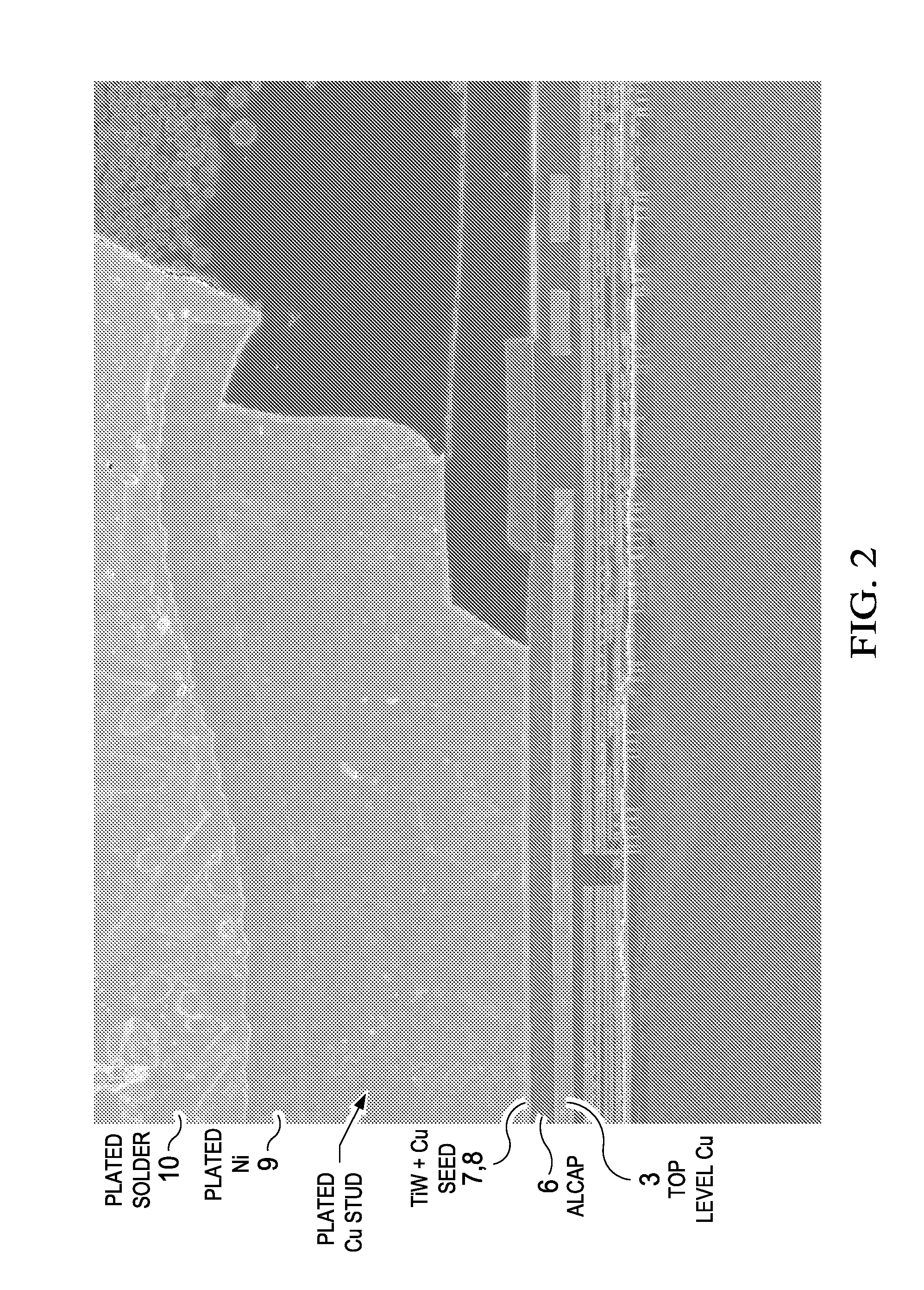
Disclosed is an under bump metallization structure including a plurality of metal or metal alloy layers formed on chip bond pads with improved reliability due to a sacrificial metal oxide and the methods of making the under bump metallization structures.

Description

CROSS-REFERENCE TO RELATED APPLICATIONS[0001]This application claims the benefit of priority under U.S.C. §119(e) of U.S. Provisional Application 61 / 908,283 (Texas Instruments docket number TI-72691PS, filed Nov, 25, 2013), hereby incorporated by reference.FIELD OF THE INVENTION[0002]This disclosure relates generally to semiconductor devices and the methods of formation, and more particularly to a reliable under bump metallization (UBM) having multiple metal or metal alloy layers.BACKGROUND OF THE INVENTION[0003]Interconnections between semiconductor-based integrated circuits, commonly referred to as “chips” and package leads are performed by wire bonding, solder bumps or tape automated bonding (TAB). Among them, the wire bonding technique is most commonly used because of its low cost. However, when the size of the chip-package interconnection scales down, the performance and reliability of wirebonding may be affected since wirebonding requires the routing of all the input / output (I...

Claims


Application Information

Patent Timeline
IPC IPC(8): H01L23/00
CPCH01L24/20H01L23/53238H01L23/53233H01L23/49838H01L21/76843H01L2924/01029H01L24/13H01L2224/11005H01L2924/014H01L2924/01028H01L2924/0132H01L24/11H01L24/03H01L24/05H01L2224/0345H01L2224/0346H01L2224/0347H01L2224/05647H01L2224/05655H01L2224/1132H01L2224/11334H01L2224/1147H01L2224/13014H01L2224/13006H01L2224/11009H01L2224/05572H01L2224/03009H01L2224/0401H01L2224/05009H01L2224/05022H01L2224/05166H01L2224/1134H01L2224/131H01L2224/13147H01L2224/05007H01L2924/00014H01L2224/05547H01L21/76883H01L21/76888
Inventor FAUST, RICHARD ALLENNGUYEN, JOSEPH
Owner TEXAS INSTR INC
Features
  • R&D
  • Intellectual Property
  • Life Sciences
  • Materials
  • Tech Scout
  • Unparalleled Data Quality
  • Higher Quality Content
  • 60% Fewer Hallucinations
Learn More