
Voltage protection and health monitoring of batteries with reference electrodes

a technology of reference electrodes and battery protection, which is applied in the direction of secondary cell servicing/maintenance, instruments, electrochemical generators, etc., can solve the problems of limiting the performance of the battery, unable to prevent damage, and difficult on-line characterization of the battery or fuel cell in the vehicl

Active Publication Date: 2015-05-28
HRL LAB +1
View PDF8 Cites 52 Cited by
  • Summary
  • Abstract
  • Description
  • Claims
  • Application Information

AI Technical Summary

Benefits of technology

This invention can benefit various commercial applications that need information about battery safety, health, and life. It is especially important for automobiles, airplanes, and other applications where battery management is critical for customer satisfaction. The invention can improve battery safety, accuracy, and reliability by measuring the battery electrode potentials. Other applications include consumer electronics, electric bicycles, power tools, aircrafts, and satellites. This invention can also impact space applications such as satellites.

Problems solved by technology

On-line characterization of batteries or fuel cells in vehicles is difficult, due to very rough noisy environments.
Current systems typically rely exclusively on voltage monitoring of the full battery cell, which is useful for identifying a problem but is often incapable of preventing damage because the system is triggered during / after the system has exceeded its threshold values.
In these systems, the only way to completely avoid damage is to establish conservative threshold values (tighten the operating limits), which limits the performance of the battery.
However, so far there hasn't been a reliable instrumentation and method to characterize each individual electrode of the battery when the battery is cycling away from equilibrium states, under a random driving profile.
In many applications, such as electric vehicles, batteries are usually driven in high rates and therefore are not around equilibrium.
However, the full cell voltage is a poor indicator of the health of each electrode.

Method used


Image

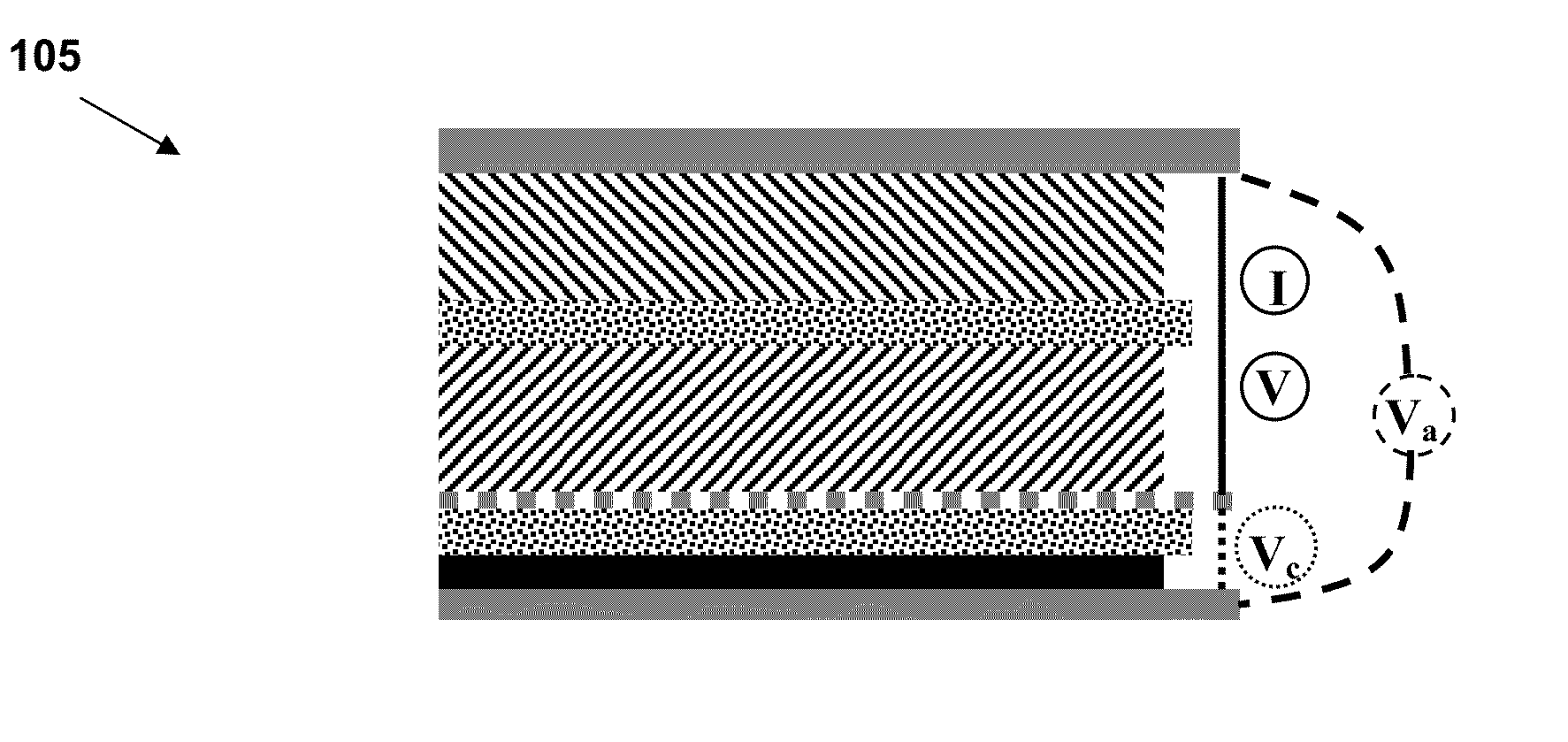
  • Voltage protection and health monitoring of batteries with reference electrodes
  • Voltage protection and health monitoring of batteries with reference electrodes
  • Voltage protection and health monitoring of batteries with reference electrodes

Examples


example 1

Charge-Discharge Profiles of a Lithium-Ion Battery Cell with a Reference Electrode

[0217]A cell is constructed with a LiNi1 / 3Co1 / 3Mn1 / 3O2 (L333)-based cathode on an Al mesh and a graphite-based anode on Cu foil. In particular, the positive electrode is composed of 84 wt % L333 (Toda Kogyo Corp, NCM-01ST), 3 wt % Super P carbon (MMM SA CARBON), 3 wt % KS6 (TIMCAL), and 10 wt % Kynar Flex 2801 (ELF ATOCHEM) and is pressed onto an Al mesh as a current collector. The negative electrode is composed of 89 wt % CGP-G8 (ConocoPhillips), 3 wt % Super P carbon (MMM SA CARBON), and 8 wt % Kynar Flex 2801 (ELF ATOCHEM) and is cast onto a copper foil. The lithium reference electrode is made from lithium metal compressed onto a copper foil. The capacities of the cathode and anode are evenly matched. The electrolyte is 1 M LiPF6 in (1:1 v / v) ethylene carbonate-dimethyl carbonate solution. Electrochemical experiments are carried out using an Arbin battery tester at a C / 10 rate with a cutoff voltage ...

example 2

Use of a Reference Electrode to Monitor Voltage and Differential Voltage of Electrodes for Enhanced Battery Management, Safety, and Health Assessment

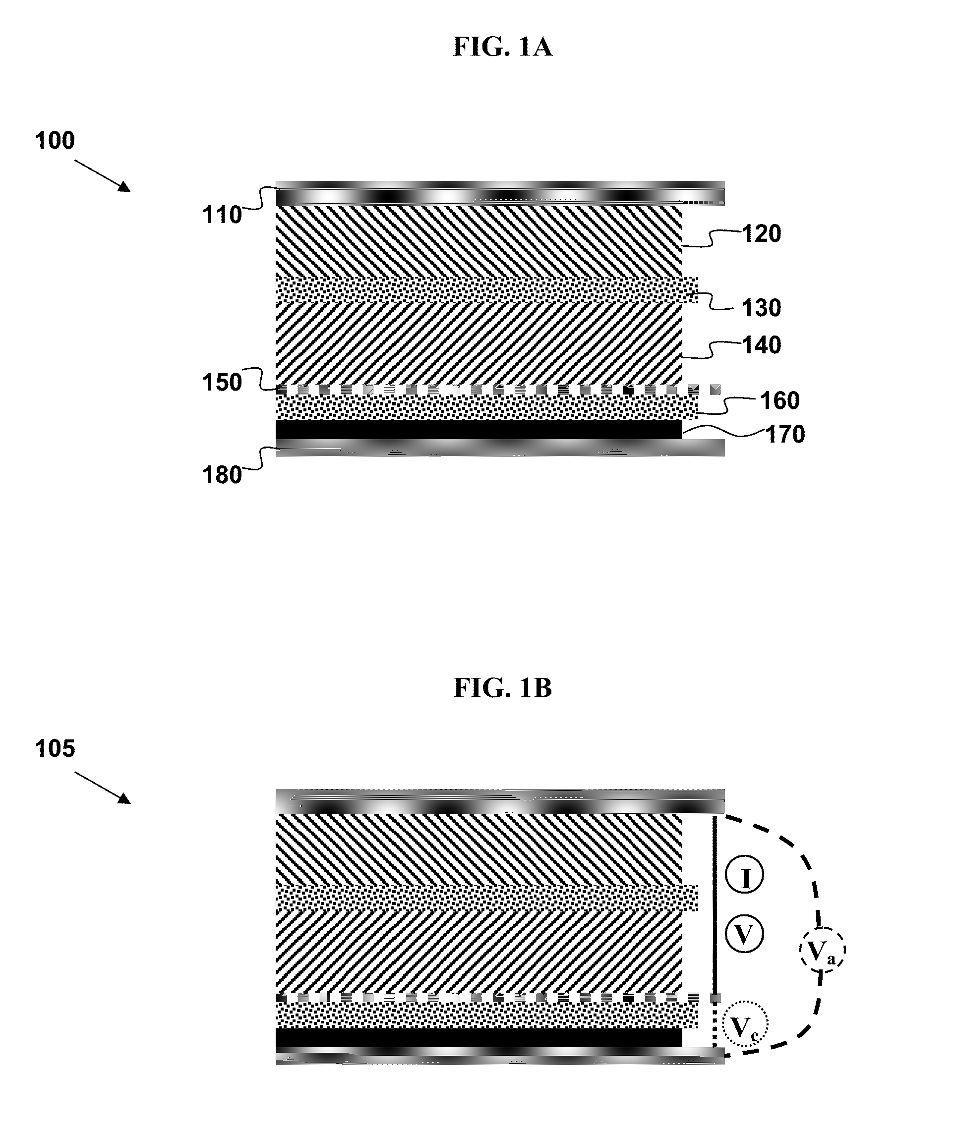
[0224]FIGS. 4A and 4B depict experimental voltage and differential voltage (dV / dQ) from the graphite-based negative electrode (FIG. 4A) and the LiNi1 / 3Co1 / 3Mn1 / 3O2 positive electrode (FIG. 4B) before (solid lines) and after (dotted lines) cycling. The voltages are measured using a lithium reference electrode in a prismatic pouch cell design as in Example 1.

[0225]As a battery ages, the voltages of the positive and negative electrodes diverge due to resistance rise and material degradation. For example, during battery charging, the voltage of the negative electrode (FIG. 4A) is depressed to a lower voltage close to 0 V, while the positive electrode voltage (FIG. 4B) rises quickly due to the increase in resistance as the battery ages.

example 3

Use of Positive and Negative Electrode Voltages for on-Line Battery Capacity Diagnostics

[0226]The voltage from individual electrodes can be used to determine each electrode's state-of-charge (SOC), during normal battery operation. These SOC values can then be used to determine electrode capacity, which tends to degrade during aging. This may be accomplished by using instances, during normal battery operation, when the current is zero (i.e., open-circuit). If this period is long enough (typically a few minutes or more), the measured voltage of each individual electrode approaches its open-circuit voltage (OCV). Using a predetermined SOC-OCV look-up table (at the appropriate temperature), we can deduce the SOC of each electrode.

[0227]The cathode capacity may be estimated according to the following derived equations. The anode equations are the same except for a change of subscripts from c (cathode) to a (anode). If two instances of open-circuit period are identified, i.e., at times ta...


PUM


Abstract

In some variations, an apparatus provides real-time monitoring of voltage and differential voltage of both anode and cathode in a battery configured with at least one reference electrode. Voltage monitors are connected to a computer programmed for receiving anode voltage signals; receiving cathode voltage signals; calculating the derivative of the anode voltage with respect to time or with respect to capacity; and calculating the derivative of the cathode voltage with respect to time or with respect to capacity. Other variations provide an apparatus for real-time assessment of capacities of both anode and cathode in a battery, comprising a computer programmed for receiving electrode voltage signals; estimating first and second electrode open-circuit voltages at two different times, and correlating the first and second electrode open-circuit voltages to first and second electrode states of charge, respectively, for each of anode and cathode. The anode and cathode capacities may then be estimated independently.

Description

PRIORITY DATA[0001]This patent application is a non-provisional application with priority to U.S. Provisional Patent App. No. 61 / 908,095, filed Nov. 23, 2013, which is hereby incorporated by reference herein.FIELD OF THE INVENTION[0002]The present invention generally relates to systems and methods to monitor the health and capacity of metal-ion batteries configured with a reference electrode.BACKGROUND OF THE INVENTION[0003]An electrochemical system is a system that either derives electrical energy from chemical reactions, or facilitates chemical reactions through the introduction of electrical energy. An electrochemical system generally includes a cathode, an anode, and an electrolyte, and is typically complex with multiple scales from nanometers to meters. Examples of these systems include batteries and fuel cells. On-line characterization of batteries or fuel cells in vehicles is difficult, due to very rough noisy environments.[0004]On-line characterization of such electrochemica...

Claims


Application Information

Patent Timeline
IPC IPC(8): H01M10/42G01R31/36H01M10/48
CPCH01M10/4285G01R31/3648G01R31/362H01M10/48G01R31/3842G01R31/392Y02E60/10G01R31/367G01N27/4161H01M10/4221G01R31/382G01R31/3835H01M10/052
Inventor WANG, SHUOQINWANG, JOHNGRAETZ, JASON A.SOUKIAZIAN, SOURENSHERMAN, ELENALIU, PINGVERBRUGGE, MARK
Owner HRL LAB
Learn More