Variable-frequency optical combs, heterodyne sensor, and process for performing spectroscopy

a technology of optical combs and heterodyne sensors, applied in the direction of optical radiation measurement, interferometric spectrometry, instruments, etc., can solve the problems of limiting the ultimate sensitivity and the use of spectroscopy

Active Publication Date: 2015-06-11
UNITED STATES OF AMERICA
View PDF7 Cites 20 Cited by
  • Summary
  • Abstract
  • Description
  • Claims
  • Application Information

AI Technical Summary

Problems solved by technology

However, due to the wide bandwidth of FOFCs, in some cases each frequency component has nanowatts or less of optical power that might limit ultimate sensitivity and use in spectroscopy.

Method used


Image

  • Variable-frequency optical combs, heterodyne sensor, and process for performing spectroscopy
  • Variable-frequency optical combs, heterodyne sensor, and process for performing spectroscopy
  • Variable-frequency optical combs, heterodyne sensor, and process for performing spectroscopy

Examples


example 1

Production of Optical Frequency Combs from Continuous Wave Radiation

[0067]Optical frequency combs (OFCs) were produced using dual-drive Mach-Zehnder modulators (MZMs, 20 GHz bandwidth). The dual-drive MZMs levelled the optical power of the resultant OFCs by attenuation of one (I or Q) of the input waveforms input into the MZMs to drive and by control a phase condition with use of an external DC bias. These parameters were set prior to a given measurement with no active feedback. FIGS. 10 and 11 show a graph of optical power versus detuning for an optical frequency comb having an 8 GHz teeth frequency spacing (FIG. 10) and 18 GHz teeth frequency spacing (FIG. 11) acquired by an optical spectrum analyzer that had a resolution of 4 GHz. The asymmetric lineshape of the teeth was a result of a limitation of the spectrum analyzer: the widths of the comb teeth are limited by the length of the time domain record. Changing various microwave components produce optical frequency combs that had...

example 2

Multiheterodyne Spectroscopy

[0068]Two OFCs (a probe comb and LO comb) were produced were produced from a single external-cavity diode laser using two dual drive MZMs. The probe comb and LO comb had comb frequency spacings that differed by δfmod=24 kHz. A sample comb was produced by passing the probe comb through a sample of CO2 gas. A fiber-coupled acousto-optic modulator (AOM) shifted the frequency of the probe comb by 99.9 MHz to move a heterodyne signal away from DC. Shifting the frequency of the probe comb reduced effects of 1 / f noise and ensured each pair of optical frequency components (teeth) corresponded to a unique RF frequency.

[0069]FIG. 12 shows a graph of intensity versus frequency for the probe comb after passing through the sample. To normalize a probe-LO heterodyne signal, a reference OFC was provided that did not interact with the gas sample. Driving the probe and reference comb AOMs at slightly different frequencies (δfAOM=12 kHz) produced two interleaved heterodyne...

example 3

Triple Comb Multiheterodyne Spectroscopy

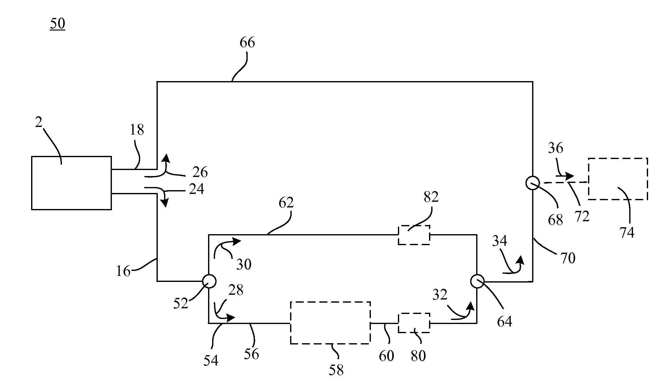
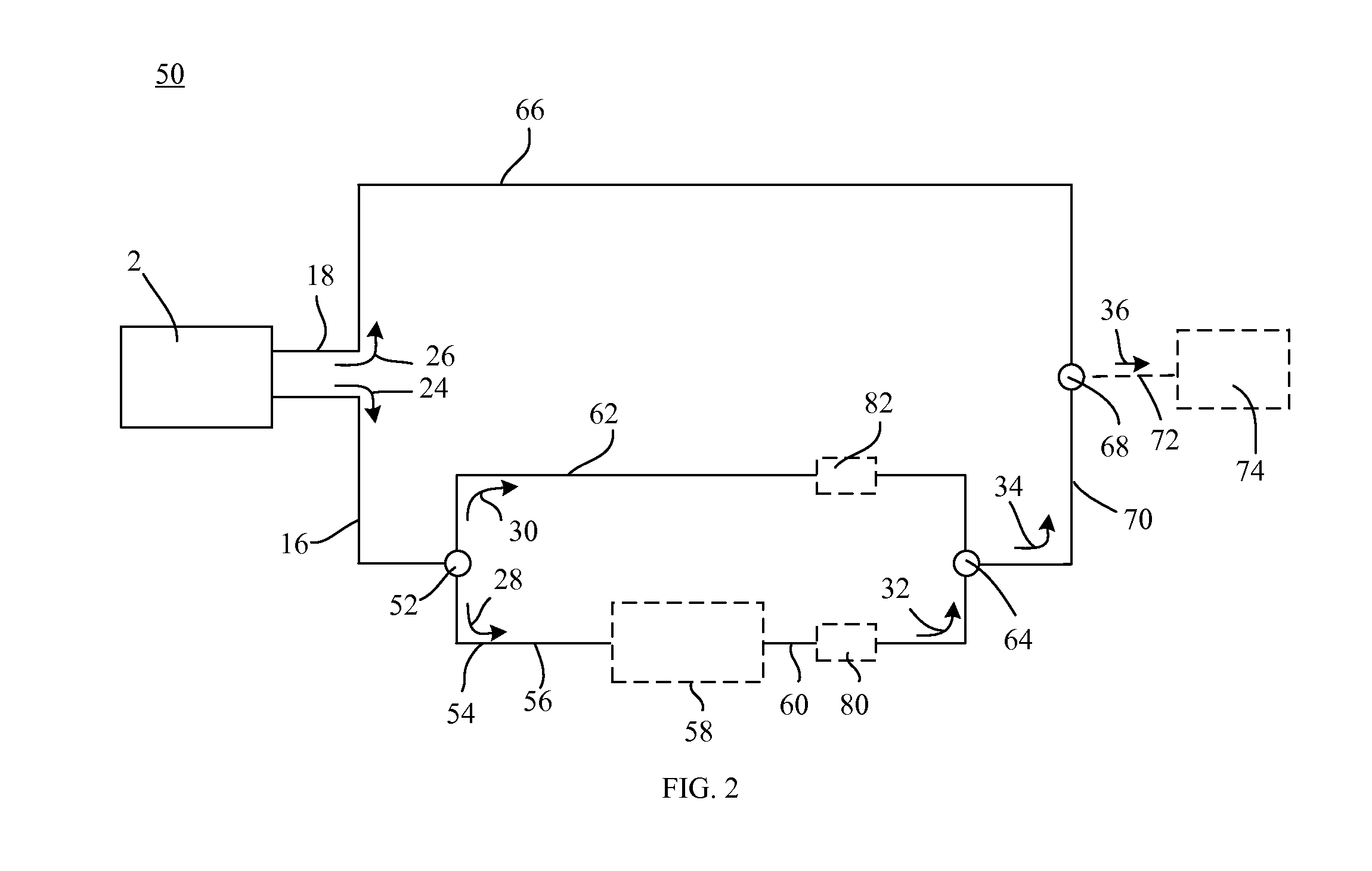
[0074]Optical frequency combs were produced according to the scheme shown in FIGS. 3,4,5 using two electro-optic phase modulators. The waveform frequencies M of first comb 24 and second comb 26 were 666.66667 MHz and 666.61667 MHz, respectively. The period of first comb is 54 nsec to generate fine teeth with spacing 18.518 MHz and the period of the second comb (LO comb) is the same as the sampling period of 2.4192 ms. The pulse shapes were initially optimized (in an iterative way using genetic algorithms) by variation of the amplitudes, phases and widths of the fundamental and two harmonics over the sampling period. The resulting heterodyne waveform at receiver 74 is Fourier transformed to give independent sets of radiofrequency combs for each of the probe and reference arms. The AOM shifts used in probe arm 54 and reference arm 62 were 251.010 MHz and 251.000 MHz, respectively, separating the probe and corresponding reference teeth in the het...


PUM


Abstract

A comb source includes a continuous wave frequency source to provide a continuous wave radiation; a first modulator in optical communication with the continuous wave frequency source; a second modulator in optical communication with continuous wave frequency source; and a waveform driver in electrical communication with the first modulator and the second modulator. A process for producing an analyte spectrum includes producing a first comb from a continuous wave frequency and a first waveform; producing a reference comb and a probe comb from the first comb; subjecting a sample to the probe comb; producing a sample comb in response to subjecting the sample to the probe comb; producing a composite comb from the reference comb and the sample comb; producing a second comb from the continuous wave frequency and a second waveform; and combining the second comb and the composite comb to produce the analyte spectrum

Description

CROSS REFERENCE TO RELATED APPLICATIONS[0001]The present application claims the benefit of U.S. Provisional Patent Application Ser. No. 61 / 928,790 filed Jan. 17, 2014, the disclosure of which is incorporated herein by reference in its entirety.STATEMENT REGARDING FEDERALLY SPONSORED RESEARCH[0002]This invention was made with United States government support from the National Institute of Standards and Technology. The government has certain rights in the invention.BACKGROUND[0003]Femtosecond optical frequency combs (FOFCs) generated from mode-locked pulsed lasers (MLL) offer a wide spectral bandwidth and ultra-narrow frequency component linewidths while serving as absolute frequency references when phase stabilized. However, due to the wide bandwidth of FOFCs, in some cases each frequency component has nanowatts or less of optical power that might limit ultimate sensitivity and use in spectroscopy. Furthermore, a comb spacing that is given by a repetition rate for a pulsed laser is l...

Claims


Application Information

Patent Timeline
Patent Type & Authority Applications(United States)
IPC IPC(8): G01B9/02G01N21/25G01J3/45G02F1/35G02F1/01
CPCG01B9/02008G02F1/3532G01N2201/06113G01J3/45G01N21/255G02F1/0121G01J3/433G01J3/453G01J2003/104G01N21/39G01N2021/399G02F2203/56H01S3/0057
Inventor PLUSQUELLIC, DAVID F.LONG, DAVID A.DOUGLASS, KEVIN O.HODGES, JOSEPH T.FLEISHER, ADAM J.
Owner UNITED STATES OF AMERICA
Why Eureka
Try Eureka