Piezoelectric element, piezoelectric vibration module, and methods of manufacturing the same
a piezoelectric and vibration module technology, applied in the field of piezoelectric vibration module, can solve the problems of poor temperature characteristics and difficulty in practical use, and achieve the effects of improving vibration displacement, stabilizing temperature characteristics, and efficiently propagating vibration
- Summary
- Abstract
- Description
- Claims
- Application Information
AI Technical Summary
Benefits of technology
Problems solved by technology
Method used
Image
Examples
example 1
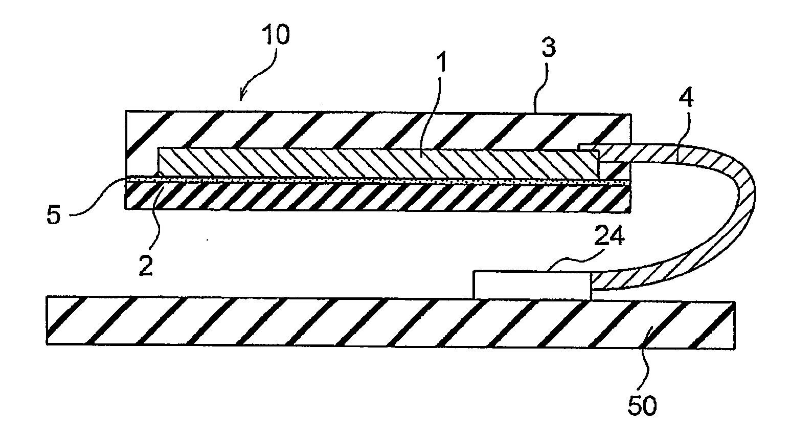
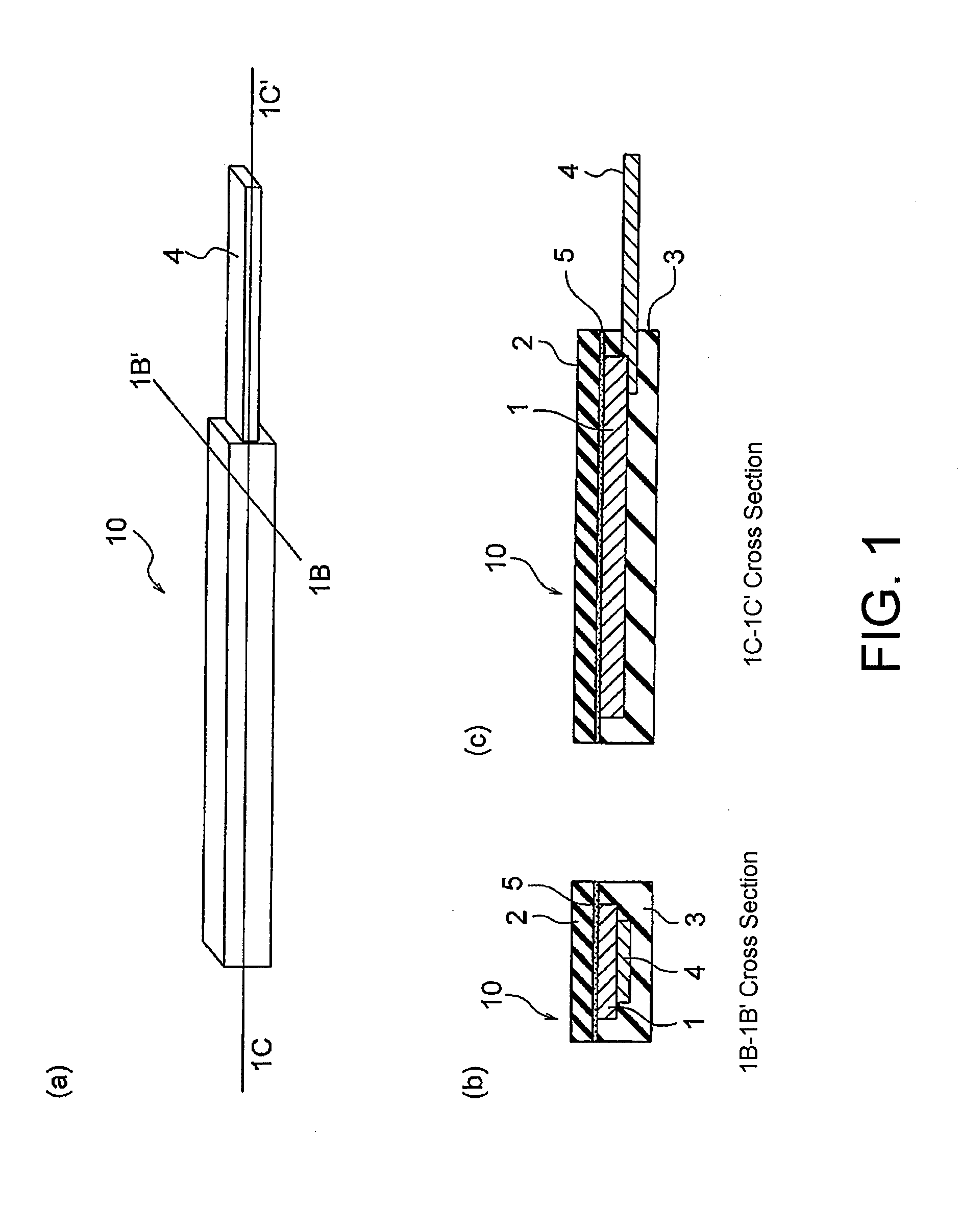
[0187]There were prepared a piezoelectric element 1 and a piezoelectric vibration module 10 having the structures shown in FIG. 1(a), FIG. 1(b), and FIG. 1(c). A silicone rubber was used as a vibration body 2 and a housing member 3 for a piezoelectric element of a piezoelectric vibration module according to an Example of this invention.
[0188]The piezoelectric vibration module according to the Example of this invention had a length of 30 mm, a thickness of 1.8 mm, and a width of 3.0 mm while the piezoelectric element 1 had a length of 27 mm, a thickness of 1.0 mm, and a width of 5.0 mm.
[0189]For comparison, use was made of a piezoelectric vibration module having the same size and molded with polyurethane as a vibration plate and a housing member.
[0190]Using a function generator and a high-frequency amplifier and inputting a driving voltage of 20Vpp and 300 to 3400 Hz, a displacement was measured by a laser displacement gauge.
[0191]The piezoelectric vibration module according to the e...
example 2
[0194]For piezoelectric vibration modules of this invention which were the same as that used in Example 1, the displacement with respect to the hardness was measured at room temperature using the same displacement gauge as in Example 1 by changing the durometer hardness (JIS K 6253) of a silicone rubber of a housing member and a vibration plate of each piezoelectric vibration module from 10 to 16. The results are shown in FIG. 10. As shown in FIG. 9, it was confirmed that the displacement (nmpp) showed an optimum value of 1500 to 2000 when the hardness of the silicone rubber was 30 to 130. By setting the durometer hardness to 30 to 130, it is possible to increase the magnitude of the vibration displacement.
example 3
[0195]Using piezoelectric vibration modules having the same structure as that used in Example 1, with silicone rubber thicknesses (one-side thicknesses) different from that in Example 1 and with the same silicone rubber thickness, the displacement with respect to the silicone rubber thickness (one-side thickness) was measured at room temperature by the same displacement measurement as in Example 1. Further, the piezoelectric vibration modules of this invention were dropped by changing the height, thereby measuring the allowable drop height based on the presence / absence of damage, crack, chipping, or the like of piezoelectric elements.
[0196]The results are shown in FIG. 11. As shown in FIG. 11, it was confirmed that, in a range of a thickness of 0.1 to 0.8 mm, the displacement (nmpp) was in a range of 1500 to 2300 and the allowable drop height was 1.5 m to 2.2 m. From this, it is possible to achieve both the vibration displacement and the drop impact resistance by setting the one-sid...
PUM
 Abstract
Description
Claims
Application Information
 - R&D
- Intellectual Property
- Life Sciences
- Materials
- Tech Scout
- Unparalleled Data Quality
- Higher Quality Content
- 60% Fewer Hallucinations
Browse by: Latest US Patents, China's latest patents, Technical Efficacy Thesaurus, Application Domain, Technology Topic, Popular Technical Reports.
© 2025 PatSnap. All rights reserved.Legal|Privacy policy|Modern Slavery Act Transparency Statement|Sitemap|About US| Contact US: help@patsnap.com


