Holding structure for concurrently holding a plurality of containers for substances for medical, pharmaceutical or cosmetic applications as well as transport or packaging container comprising the same

a holding structure and container technology, applied in the direction of packaging foodstuffs, packaged goods types, lighting and heating apparatus, etc., can solve the problems of limited processing speed, undesired abrasion, contamination of the interior, etc., and achieve the effect of flexible loading and processing stations and effective loading

Active Publication Date: 2015-06-18
SCHOTT PHARMA AG & CO KGAA
View PDF6 Cites 34 Cited by
  • Summary
  • Abstract
  • Description
  • Claims
  • Application Information

AI Technical Summary

Benefits of technology

[0011]It is an object of the present invention to further enhance a holding structure for concurrently holding a plurality of containers for cosmetic, medical or pharmaceutical applications, particularly of glass or plastic vials, so that the containers can be retained in a simple and reliable manner and can be sterile packaged, unpackaged and processed cost efficiently. According to a preferred further aspect of the present invention such a holding structure shall be configured in particular for a further processing of the containers while these are held in the holding structure.
[0012]According to a further aspect of the present invention, which is independent of the aforementioned aspects, furthermore a holding structure for concurrently holding a plurality of containers for cosmetic, medical or pharmaceutical applications, in particular of glass or plastic vials, is to be enhanced further to the effect that processing stations or stations for treatment, such as a freeze-drying facility, can be loaded with holding structures and unloaded more easily and reliably.

Problems solved by technology

This limits the speed of processing that can be achieved.
Particularly in the isolation of the containers by means of cell wheels or the like, it always occurs that individual containers abut uncontrolled, which results in an undesired abrasion and subsequently in a contamination of the interior volume of the containers or of the processing station and in an impairment of the outer appearance of the containers which is undesirable.
During the evacuation and the subsequent opening of the plastic tube, however, the medication containers may slip sideways, increasing the efforts required for automation for processing further the medication containers.
In addition, the medication containers may still collide uncontrollably after opening of the plastic tube, resulting in the aforementioned disadvantages.
A further processing of the medication containers in batches while being accommodated in a holding structure as outlined above is not possible.
Thus, the holding structure is of very limited use for vials having high tolerances or having different outer diameters.
Furthermore, the vials cannot be retained free of tension in the holding structure, which may result in an undesired bulging of the holding structure, in particular during the processing.
Therefore, the use of such holding structures is not flexible enough for vials having larger tolerances and / or different outer diameters.
In any case, a direct contact of the bottoms of the medication containers, in particular of the bottoms of vials, is not possible for the conventional holding structures.
However, this complicates the further processing of the medication containers particularly when their content is to be subjected to a freeze-drying process (also known as lyophilization or sublimation drying).
Furthermore, a further processing of the medication containers directly in the holding structures is not possible, because they are either retained there rigidly or not accessible to a sufficient degree for further processing, for which reason the medication containers conventionally always need to be taken out of the holding structure for a further processing, which is time-consuming and expensive.

Method used


Image

  • Holding structure for concurrently holding a plurality of containers for substances for medical, pharmaceutical or cosmetic applications as well as transport or packaging container comprising the same
  • Holding structure for concurrently holding a plurality of containers for substances for medical, pharmaceutical or cosmetic applications as well as transport or packaging container comprising the same
  • Holding structure for concurrently holding a plurality of containers for substances for medical, pharmaceutical or cosmetic applications as well as transport or packaging container comprising the same

Examples


first embodiment

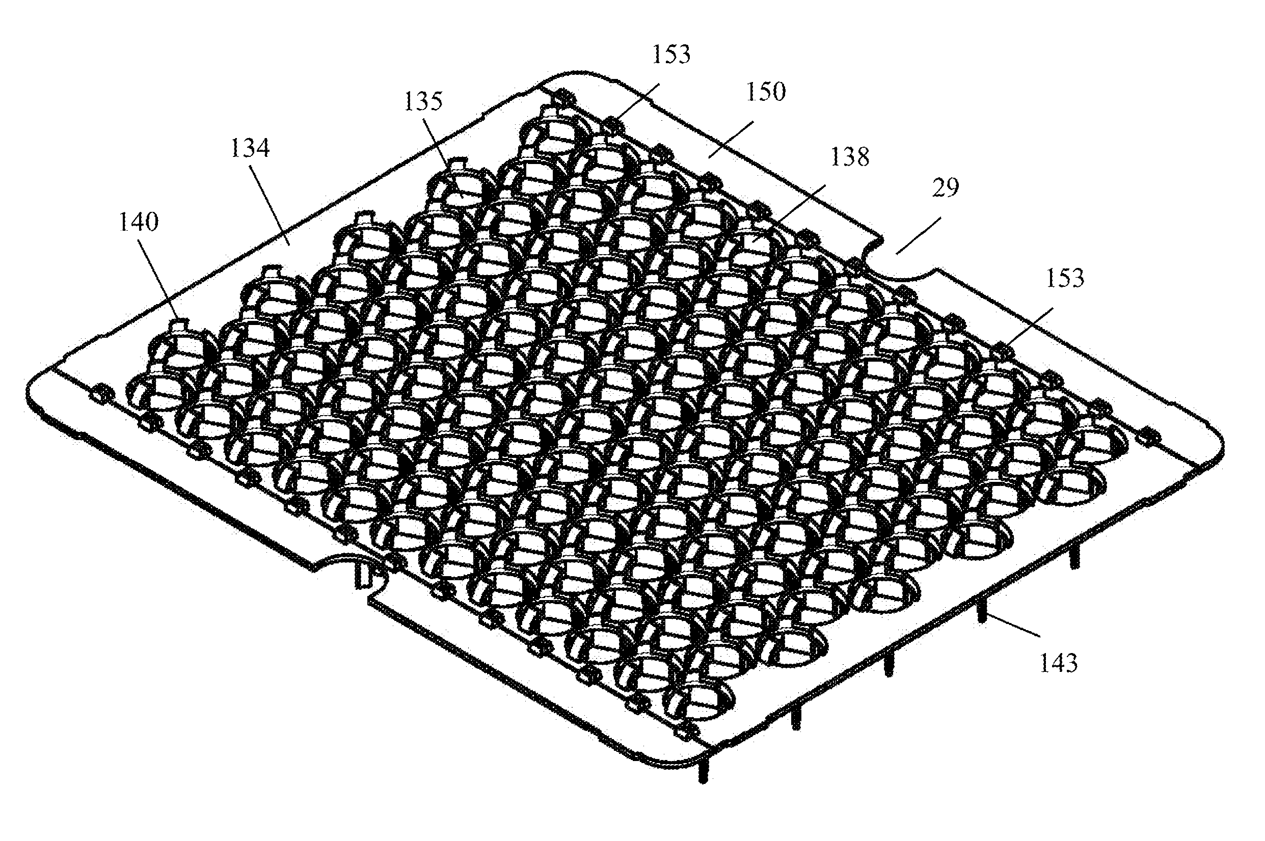
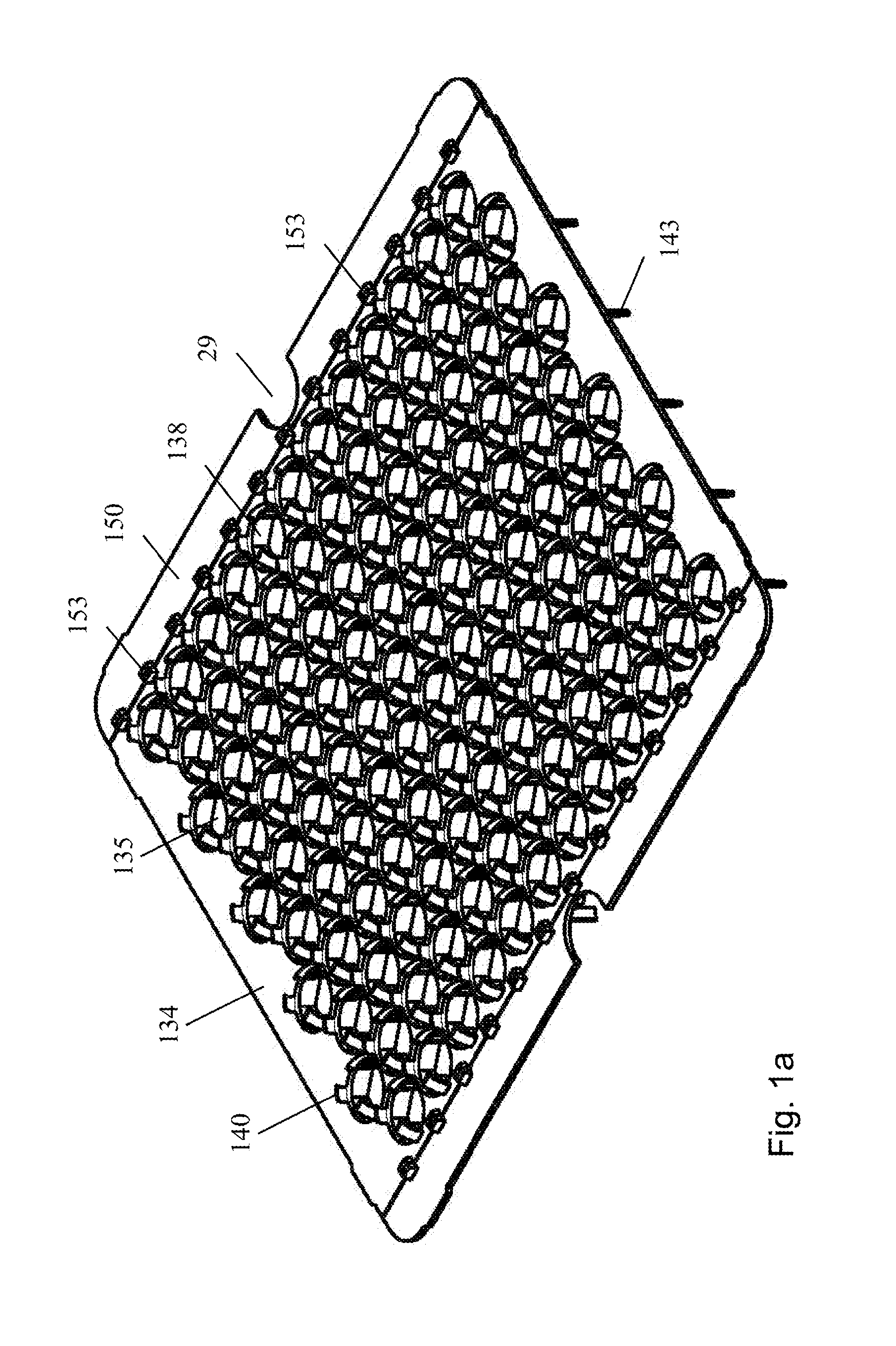
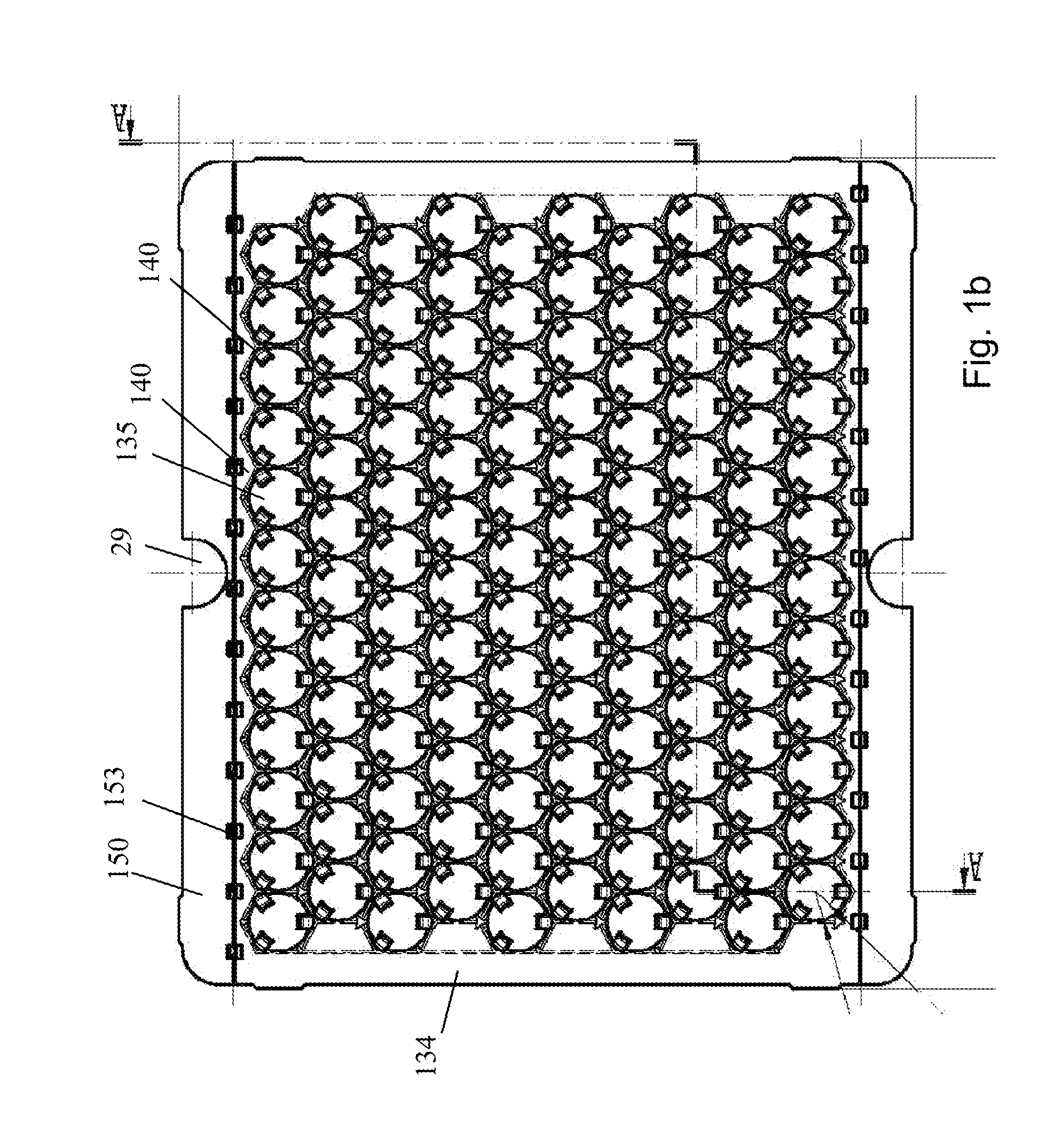
[0079]For concurrently holding a plurality of containers, according to the present invention, as shown in FIGS. 1a and 1b, a planar rectangular carrier 134 is provided that is formed of a plastic material, for example by punching or injection molding, and comprises a plurality of apertures 135 for accommodating the glass vials 2. The apertures 135 are arranged in a regular two-dimensional array, in the illustrated embodiment in a matrix array of rows and columns extending perpendicularly, which are arranged at equidistant intervals and regularly offset to each other in a periodic arrangement.

[0080]The apertures 135 are delimited by side walls 138 (see FIG. 1d) on the lower side of the carrier 134. According to FIG. 1b, resilient holding tabs 140 protrude arcuately from the upper side of the carrier 134, if viewed in a plan view, into the associated apertures 135. The resilient holding tabs 140 and the side walls 138 are preferably formed integrally with the planar carrier 134, e.g. ...

second embodiment

[0093]For the transport and packaging of the holding structure described above together with the containers accommodated therein, a transport and packaging container 10 is used, such as this is schematically shown in FIG. 2a for a holding structure or carrier 134 according to the present invention. According to FIG. 2a the transport and packaging container 10 is substantially box-shaped or trough-shaped and comprises a bottom 11, a circumferential side wall 12 extending perpendicularly, a step 13 projecting substantially perpendicularly, a circumferential upper side wall 14 and an upper edge 15 on which a flange is formed. Conveniently, the corners 16 of the transport and packaging container 10 are rounded. The upper side wall 14 may be formed inclined at a slight angle of inclination relative to a line perpendicular to the bottom 11 in order to facilitate the insertion of the holding structure 134. Such a transport and packaging container 10 is preferably formed of a plastic materi...


PUM

PropertyMeasurementUnit
angleaaaaaaaaaa
volumeaaaaaaaaaa
volumeaaaaaaaaaa

Abstract

A holding structure for concurrently holding a plurality of containers for substances for cosmetic, medical or pharmaceutical applications, in particular of vials, is provided. The holder includes a carrier having a plurality of apertures or receptacles into which the containers can be inserted and holding means for holding the containers in the apertures or receptacles. The holding means has at least two holding tabs, which are provided at the edge of a respective aperture or receptacle and protrude from an upper side of the carrier for holding the respective container. The holding tabs are resiliently pivoted or folded back as the containers are inserted into the apertures or receptacles and so that the holding tabs are matched to the containers such that these are held by the holding tabs with a radial clearance and low tension.

Description

CROSS REFERENCE TO RELATED APPLICATIONS[0001]This Application is a continuation of International Application No. PCT / EP2013 / 059297 filed on May 3, 2013, which claims the priority of German Patent application No. 10 2012 106 341.9 filed on Jul. 13, 2012, claims the priority of German Patent application No. 10 2012 108 215.4 filed on Sep. 4, 2012, claims the priority of German Patent application No. 10 2012 110 547.2 filed on Nov. 5, 2012, and claims the benefit of U.S. Application Ser. No. 61 / 696,457 filed on Sep. 4, 2012, the contents of all which are hereby incorporated in their entirety by way of reference.FIELD OF INVENTION[0002]The present invention relates generally to the concurrent holding of a plurality of containers, which serve for storing substances for medical, pharmaceutical or cosmetic applications, in particular of vials, and relates in particular to the concurrent holding of a plurality of such containers in a holding structure in a simple and reliable manner and in ...

Claims


Application Information

Patent Timeline
Patent Type & Authority Applications(United States)
IPC IPC(8): B65D1/36
CPCB65D1/36B65D25/108A61J1/16A61J7/0069B01L9/06B65B3/003B65B7/2892B65B21/18B65B43/42B65B61/207B65D71/50F26B5/06F26B25/001
Inventor WISSNER, KAIDEUTSCHLE, GREGOR FRITZKOCH, KRISTOPHER
Owner SCHOTT PHARMA AG & CO KGAA
Why Eureka
Try Eureka