
Eureka
For R&D, Eureka makes reading and utilizing patents & technical documents easy.
Eureka AIR
Designed for self-driven R&D workflows. Generate viable solutions, solve complex R&D challenges, empower your innovation with AI.

Eureka Materials
Designed for material experts only. Revolutionize your material R&D, from search, analyze, to developing new materials.

TechResearch
Generate reliable direction feasibility study reports for your R&D in just a few steps.

TechSeek
Discover and master advanced knowledge NOW. Basics, ideas, possibilities, all at once.

TechMind
As an expert in R&D Theories, TechMind can generates customized viable solutions instantly.

TechRisk
Analyze your overall solution with one click, know your potential R&D risks in advance.

TechMonitor
Get weekly tech updates, stay abreast of the latest tech innovations and key insights.
System and methods for engine air path condensation management
- Summary
- Abstract
- Description
- Claims
- Application Information
AI Technical Summary
Benefits of technology
Problems solved by technology
Method used
Image

Examples
second embodiment
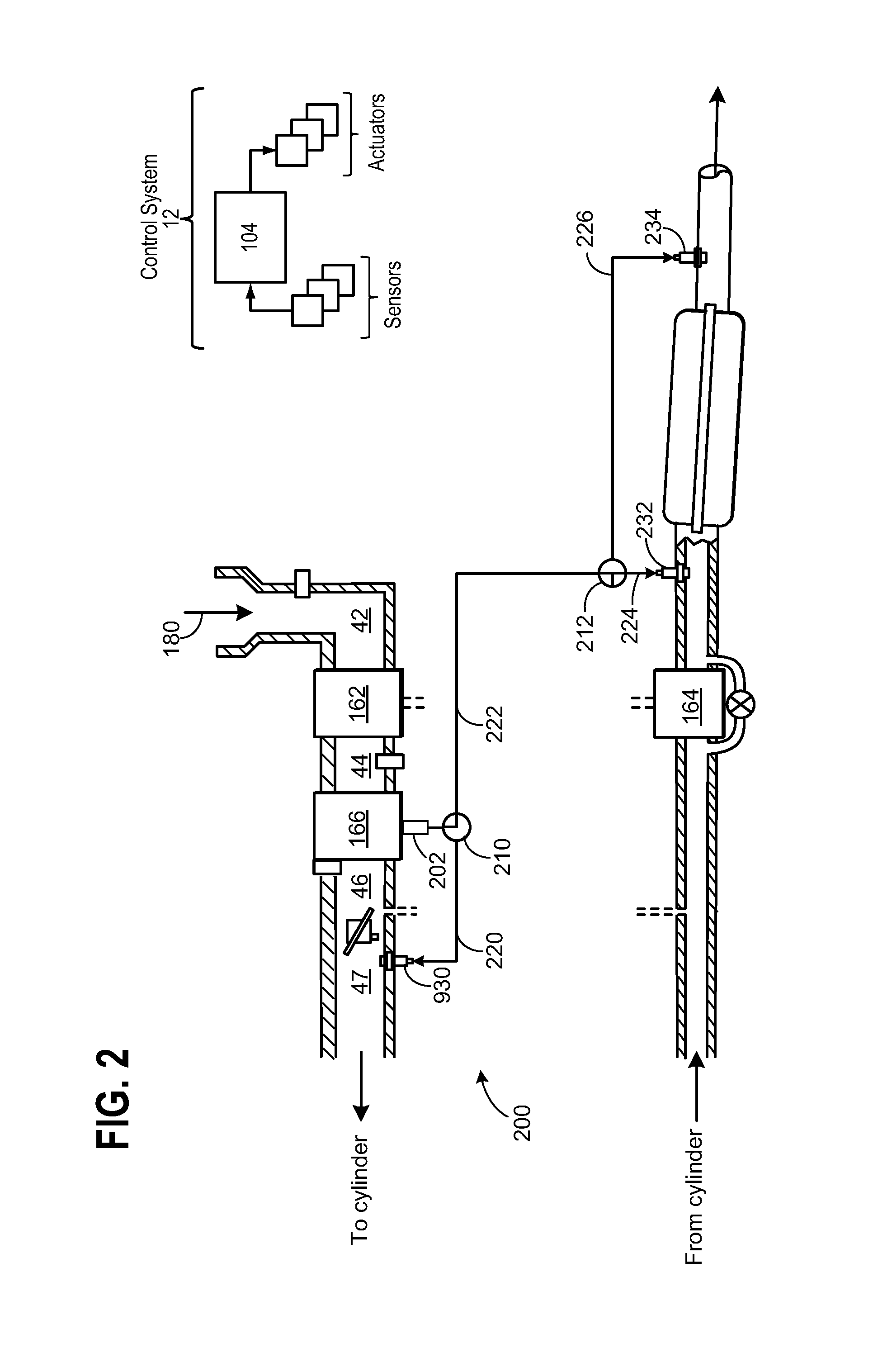
[0066]Condensate collected at the bottom of CAC 166, may then be re-introduced to the engine system at one of three position based on the type of contaminate sensed in the condensate. As mentioned above, the condensation management system further includes accumulator 902 for storing pressurized air. Thus, the method comprises routing air from a compressor through a heat exchanger to a combustion chamber of the engine; coupling condensate formed in the heat exchanger through a passage coupled to the combustion chamber; accumulating a portion of the compressed air in an accumulator; and when the engine output is below a predetermined amount, coupling a part of the accumulated air through the passage into the combustion chamber, wherein said compressor is driven by a turbo positioned in the engine exhaust, or by a mechanical coupling to a crankshaft or a camshaft of the engine.
[0067]As shown in the example of FIG. 9, accumulator 902 is coupled to the condensation management system in ...
third embodiment
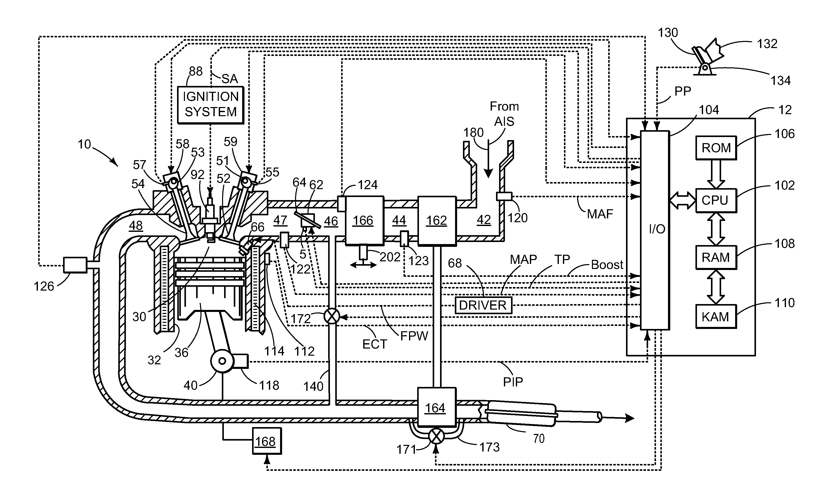
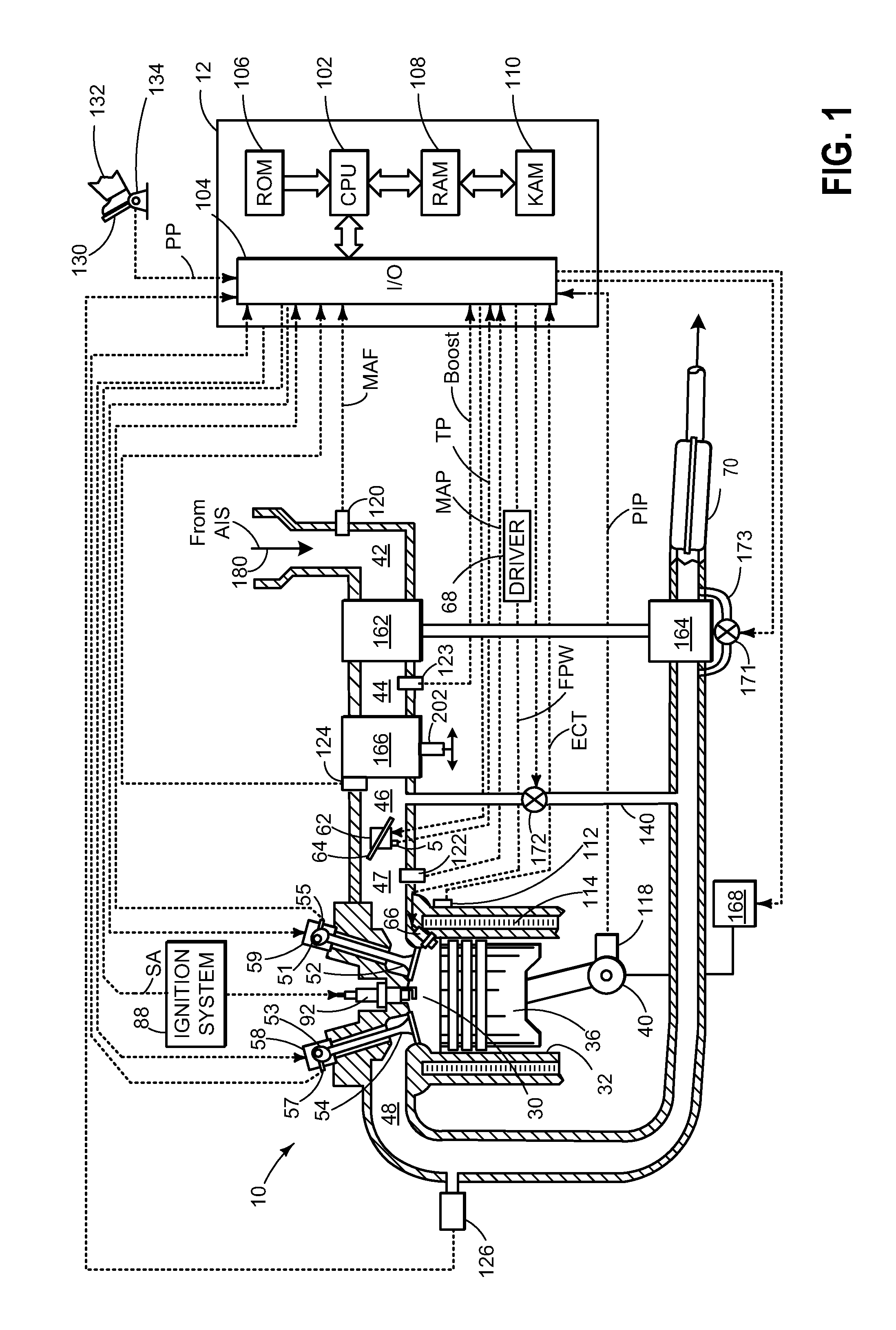
[0082]In the inline engine the collection area is located within intake manifold 47. Therefore, condensate is collected in condensate reservoir 1502 that is re-located to the lowest point within intake manifold 47. As such air that enters CAC inlet tank 42 may be cooled as it flows through CAC 1566, which is shown as a water to air charge air cooler. Then, as the airflow continues through intake manifold 47, condensate may collect at reservoir 1502. As described above, reservoir 1502 may be configured to include inlet tank assembly 202 for routing said collected condensate throughout engine 10 in the manner already described. In addition, accumulator 902 may be reconfigured based on the structure of the engine and intake system. For example, FIG. 15, shows accumulator inlet 910 in communication with CAC 1566 outlet tank 45. Therefore, airflow within the system may be directed to the auxiliary canister to increase the stored boost pressure within accumulator 902 in the same manner d...
PUM
 Abstract
Description
Claims
Application Information
 - R&D Engineer
- R&D Manager
- IP Professional
- Industry Leading Data Capabilities
- Powerful AI technology
- Patent DNA Extraction
Browse by: Latest US Patents, China's latest patents, Technical Efficacy Thesaurus, Application Domain, Technology Topic, Popular Technical Reports.
© 2024 PatSnap. All rights reserved.Legal|Privacy policy|Modern Slavery Act Transparency Statement|Sitemap|About US| Contact US: help@patsnap.com