Welding method and weld
a welding method and welding technology, applied in the field of welding methods and welds, can solve the problems of mesh member interposed between, limit the space saving attempt, and twist the joint surface of the lower member, and achieve the effect of promoting the increase of welding speed
- Summary
- Abstract
- Description
- Claims
- Application Information
AI Technical Summary
Benefits of technology
Problems solved by technology
Method used
Image
Examples
first exemplary embodiment
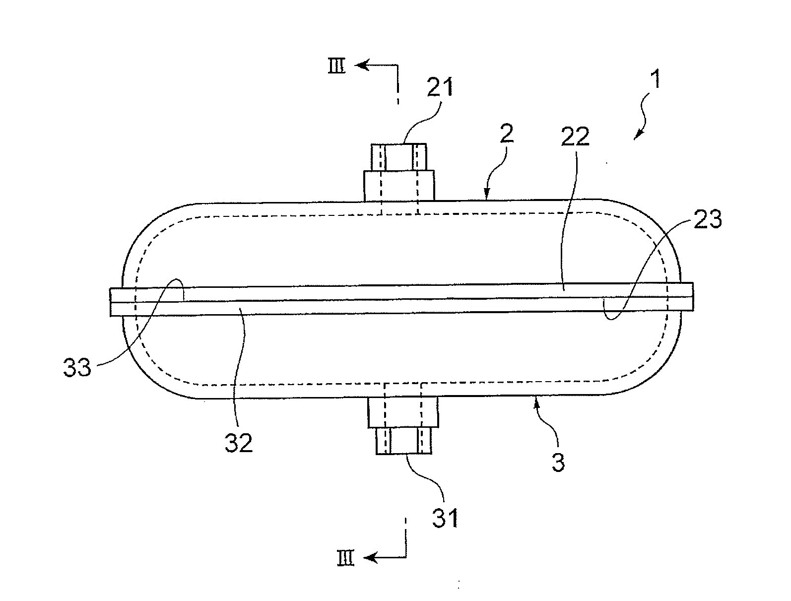
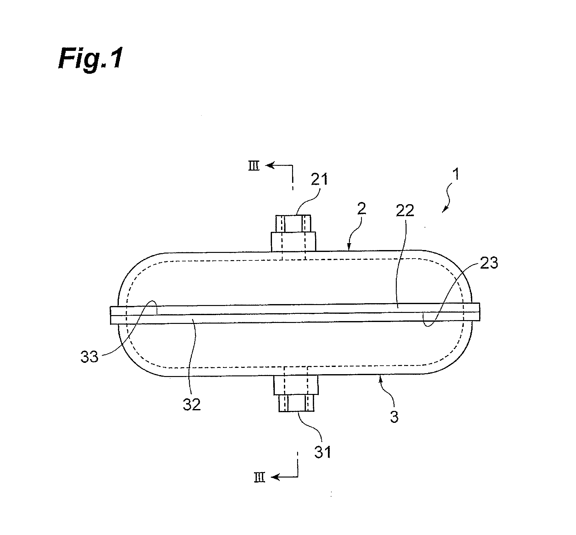
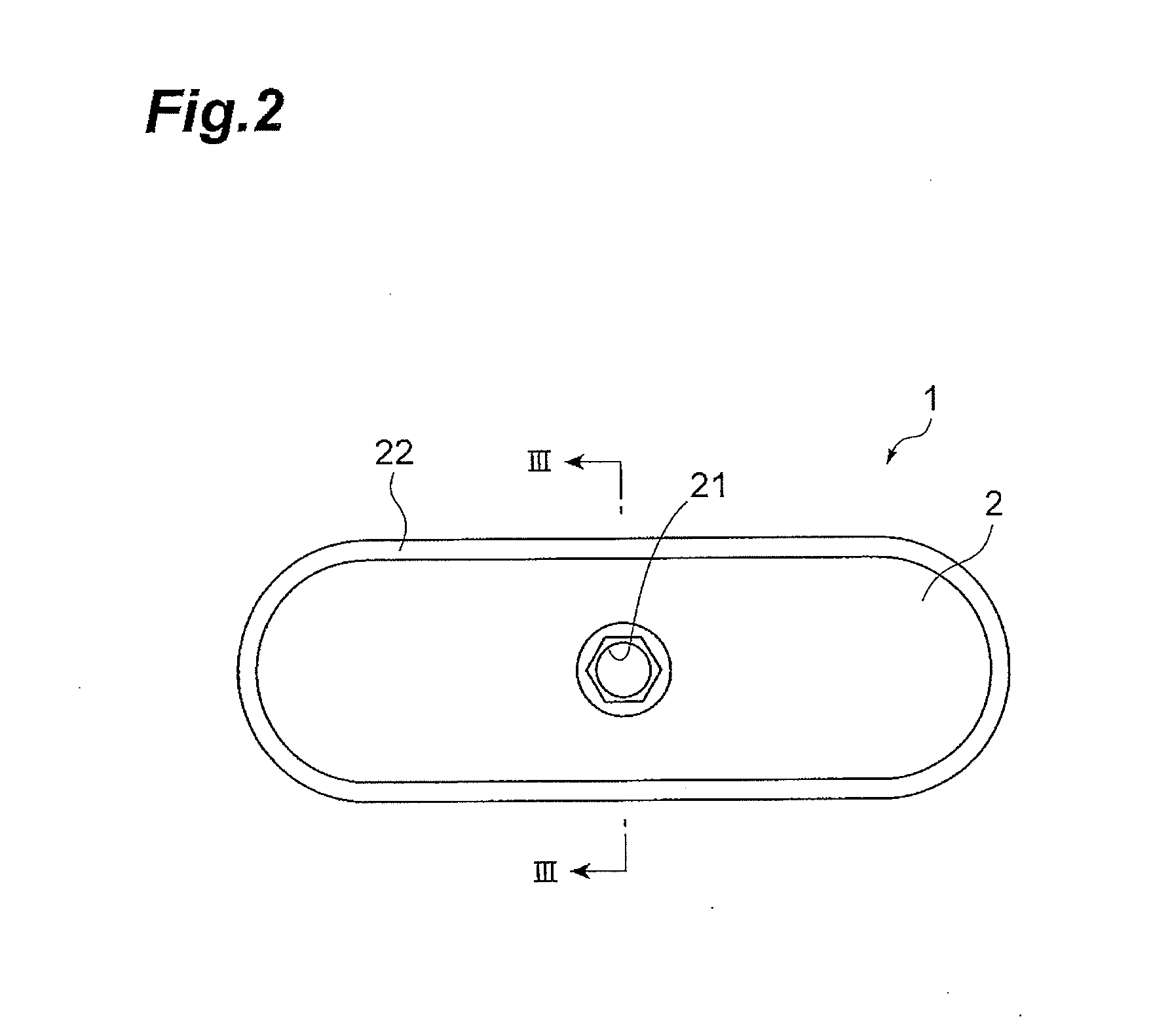
[0037]The first exemplary embodiment is to apply the present invention to an oil strainer. FIG. 1 is a front view diagram of an oil strainer related to the exemplary embodiment. FIG. 2 is a plan view diagram of the oil strainer related to the exemplary embodiment. FIG. 3 is a cross-sectional diagram of the oil strainer illustrated in FIG. 1 and FIG. 2, which is cut along the III-III line. FIG. 4 is a cross-sectional diagram of the oil strainer illustrated in FIG. 3, which is cut along the IV-IV line. FIG. 5 is a partially magnified diagram of the oil strainer illustrated in FIG. 3. FIG. 6 is a partially magnified diagram of the oil strainer illustrated in FIG. 4.
[0038]As illustrated in FIG. 1 to FIG. 3, an oil strainer 1 related to the present exemplary embodiment includes a first container unit 2 that constitutes a first resin layer; a second container unit 3 that constitutes a second resin layer; and a mesh member 4 that constitutes a metal layer. The oil strainer 1 is produced by...
second exemplary embodiment
[0062]Next, a second exemplary embodiment is explained. The second exemplary embodiment is basically the same as the first exemplary embodiment, but is different from the first exemplary embodiment only in the materials of the first container unit 2 and the second container unit 3, and in the method for laser welding. For this reason, in the following descriptions, only the differences from the first exemplary embodiment will be described, while the same descriptions applicable to the first exemplary embodiment will not be repeated.
[0063]In the second exemplary embodiment, the first container unit 2 and the second container unit 3 are formed using a light semitransmissive resin that is used in the ACW (Absorbance Control Welding) method. The ACW method is a laser welding method that has been suggested by Orient Chemical Industries Co., Ltd. (see Japanese Patent No. 4102424). Specifically, it is a method in which a light semitransmissive resin having an absorbance material or the lik...
third exemplary embodiment
[0079]Next, a third exemplary embodiment is explained.
[0080]The third exemplary embodiment relates to a welding method for interposing a metal layer having pores formed therein between a first resin layer and a second resin layer, and welding the first resin layer and the second resin layer.
[0081]For the first resin layer and the second resin layer, the same resins as those used in the first container unit 2 and the second container unit 3 of the first exemplary embodiment or the second exemplary embodiment, can be used.
[0082]The metal layer may have any shape as long as the metal layer has pores formed therein. Regarding the metal layer, for example, the same mesh member as the mesh member 4 of the first exemplary embodiment and the second exemplary embodiment, as well as a metal wire or a metal powder can be used.
[0083]When a metal powder is used as the metal layer, the metal layer is easily interposed between the first resin layer and the second resin layer by incorporating the m...
PUM
| Property | Measurement | Unit |
|---|---|---|
| porosity | aaaaa | aaaaa |
| porosity | aaaaa | aaaaa |
| porosity | aaaaa | aaaaa |
Abstract
Description
Claims
Application Information
 - R&D
- Intellectual Property
- Life Sciences
- Materials
- Tech Scout
- Unparalleled Data Quality
- Higher Quality Content
- 60% Fewer Hallucinations
Browse by: Latest US Patents, China's latest patents, Technical Efficacy Thesaurus, Application Domain, Technology Topic, Popular Technical Reports.
© 2025 PatSnap. All rights reserved.Legal|Privacy policy|Modern Slavery Act Transparency Statement|Sitemap|About US| Contact US: help@patsnap.com


