
Transfer chute

Active Publication Date: 2015-07-09
GULF CONVEYOR SYST
View PDF5 Cites 8 Cited by
  • Summary
  • Abstract
  • Description
  • Claims
  • Application Information

AI Technical Summary

Benefits of technology

The patent text explains the importance of considering the stall angle when designing transfer chutes for complex ores, particularly cohesive ores. Traditionally, transfer chutes had to have angles above 70 degrees to prevent blockages and wear. This resulted in poor material presentation, which led to problems like dust, spillage, and belt damage. However, the text presents a new design that optimizes the performance life of the transfer components. The new design allows for a higher stall angle, reducing build-up and blockages while improving material presentation and reducing wear. This results in higher system capacity and improved overall performance.

Problems solved by technology

Transfer chutes, particularly in industries that are handling abrasive ores or ores that could be described as complex due to their variability in size, moisture content and material shape, are a major burden to maintenance.
They can also be a major constraint to production if they do not have the capacity of the conveyor system in which they operate and through the maintenance needs that require scheduled and un-scheduled maintenance.
Indeed, issues associates with transfers chutes are considered to be a major constraint to production in bulk materials handling industry.
The design of transfer chutes is a fundamental issue in meeting such a need.
Further there was a capital cost penalty in going to very wide conveyors so developing transfers that could handle higher material volumes when the belts were running much faster had significant capital cost implications.
In applying these principles to transfer chute design, a number of issues were raised, including:(a) The accurate calculation of the material flow trajectory off the head pulley of the belt of the discharge belt conveyor.
Using fluid flow principles and the Coulomb friction model for sized washed coal did create reliable transfer chute designs which led to many attempts to utilise “Hood and Spoon” transfer chutes for broader applications with questionable outcomes.
The design issues encountered particular problems including:(a) Identifying that the trajectory models being used were not accurate.
In other words, it was not possible to take a sample of the material being processed and attribute physical properties to it for use in transfer chute design by re-sizing the material, as was often done by others as part of an assessment of the ore characteristics.
Conversely these same particles could create dust issues in the absence of moisture.(d) Highly abrasive ores in general as they create maintenance issues that must be managed.(e) Lump sizes greater that 150 mm.(f) Material containing cohesive or adhesive contaminants.

Method used


Image

  • Transfer chute
  • Transfer chute
  • Transfer chute

Examples


Embodiment Construction

[0132]In order to design a transfer chute according to the invention, there are two very important issues that must be addressed. These issues are: (1) the calculation of the material trajectory from the discharge belt into the body of the transfer; and (2) the understanding and development of a flow model for the bulk material being handled such that the elements of the transfer chute can be correctly designed.

[0133]There are published trajectory calculation models that will allow the accurate prediction of the material trajectory. The applicants have their own proprietary method that is used for the trajectory calculations. By way of example, the trajectory of a material flow into a transfer chute is calculated in accordance with methodology disclosed in the aforementioned publication “The Transfer Chute Design Manual for Conveyor Belt Systems”.

[0134]Developing a flow model for various ore types is a very complex science. Conventionally the methodology has been an extension of tec...


PUM


Abstract

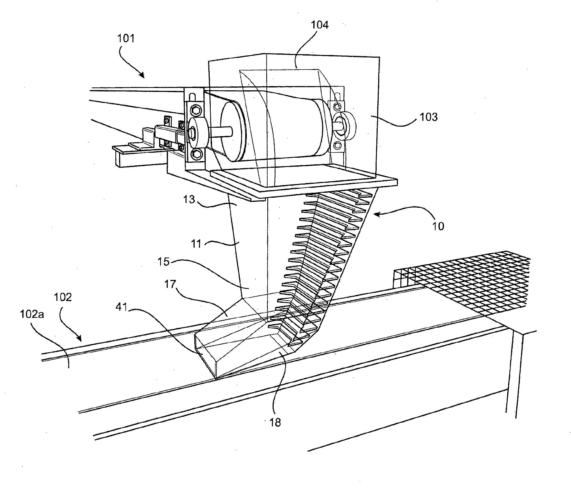
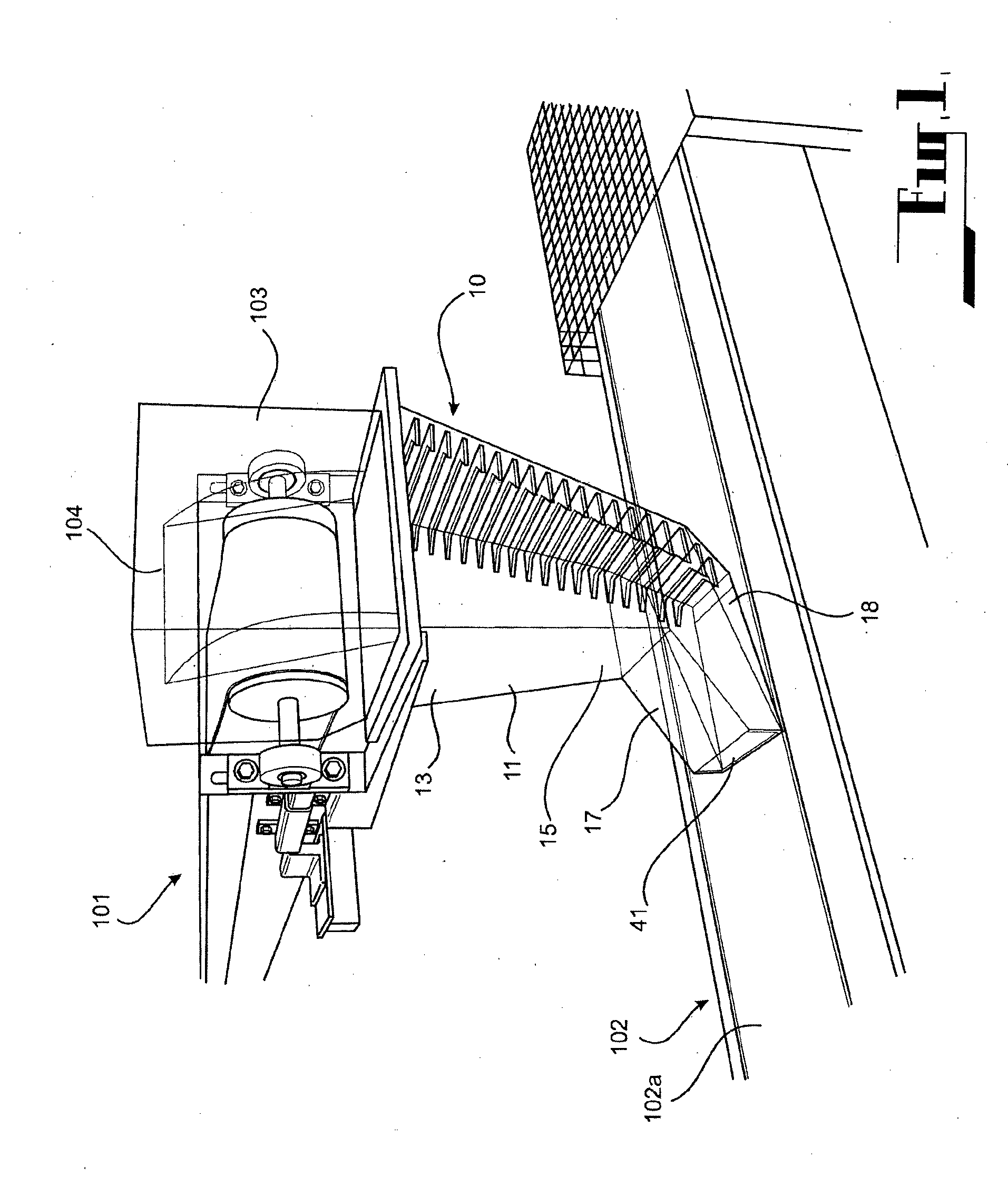
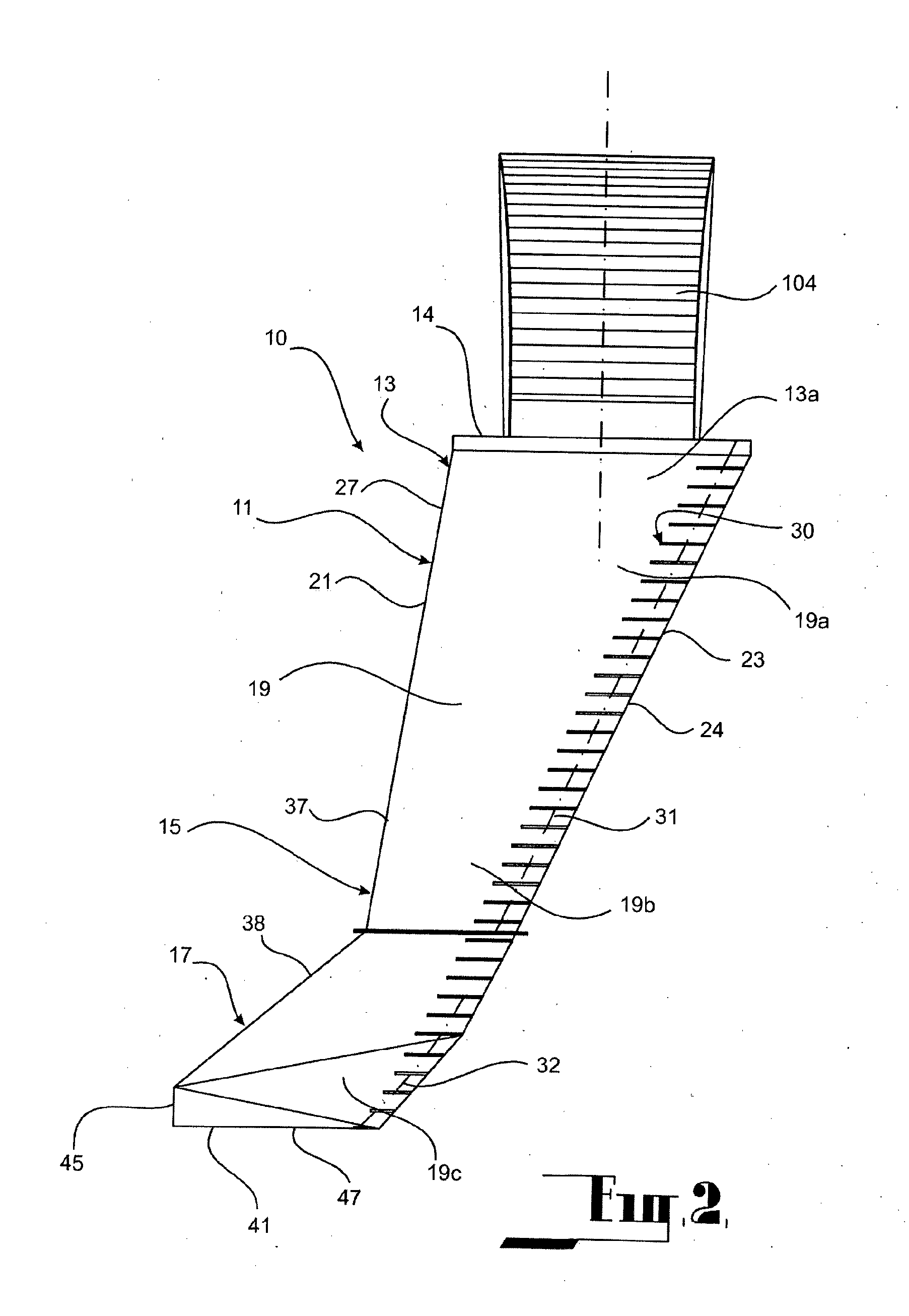
A transfer chute (10) for use in bulk materials handling operations, and also a methodology for designing such a transfer chute, a method of constructing the transfer chute, and a method of transferring bulk materials between two locations using the transfer chute. The transfer chute (10) comprises a chute body (11) defining a flow pathway (19), with an upper section (19a) of the flow pathway accommodating accelerating flow to maintain dense granular flow regime, an intermediate section (19b) of the flow pathway providing consolidated flow in which the flow rate is retarded in a controlled manner avoiding creation of flow turbulence, and a lower section (19c) of the flow pathway in which flow is further retarded to create a controlled accumulation and build-up of material upwardly from the lower section.

Description

TECHNICAL FIELD[0001]This invention relates to a transfer chute for use in bulk materials handling operations. In particular, the invention relates to a methodology for designing a transfer chute, a method of constructing a transfer chute, a transfer chute itself and a method of transferring bulk materials between two locations.BACKGROUND ART[0002]The following discussion of the background art is intended to facilitate an understanding of the present invention only. The discussion is not an acknowledgement or admission that any of the material referred to is or was part of the common general knowledge as at the priority date of the application.[0003]A transfer chute can be described as any static interface between two conveyor belts or between a piece of operating equipment (such as a screen or crusher) and a conveyor belt. Transfer chutes are an integral part of a conveyor system and such systems are commonly used and relied upon in the bulk materials handling industry.[0004]Transf...

Claims


Application Information

Patent Timeline
IPC IPC(8): B65G11/16B65G11/20G06F17/50B65G11/02
CPCB65G11/16G06F17/50B65G11/206B65G11/026B65G11/166B65G47/18B65G47/19G06F30/00
Inventor BENJAMIN, COLIN WILLIAM
Owner GULF CONVEYOR SYST
Learn More