Wind/tidal power generation bearing

a technology of wind and tide, which is applied in the direction of roller bearings, machines/engines, mechanical equipment, etc., can solve the problems of increasing the size of the nacelle due to an increase in the axial length, and reducing the size of the power generator, so as to achieve the effect of enhancing the prevention of lubricant leakage, preventing leakage, and easily mounting the sealing devi

Inactive Publication Date: 2015-07-09
NTN CORP
View PDF27 Cites 10 Cited by
  • Summary
  • Abstract
  • Description
  • Claims
  • Application Information

AI Technical Summary

Benefits of technology

[0026]A sealing device may be provided at a gap defined between the inner and outer rings. During bearing operation, a bearing pumping action that the lubricant moves from the small-diameter side portion of the inner ring raceway surface to the large-diameter side portion thereof is alleviated at the gap defined between the inner and outer rings. Since the sealing device is provided at the gap, leak of the lubricant can be effectively prevented.
[0027]An annular groove or a stepped portion in the form of a level difference becomes a recess and a projection between the inner and outer rings may be formed at an axial end of the inner and outer rings, and the sealing device may be mounted in the annular groove or the step. In this case, it is possible to easily mount the sealing device at the axial end of the inner and outer rings at which there is the annular groove or the step.
[0028]A lubricant reservoir portion configured to store a lubricant may be provided in the inner and outer rings and at a portion from the gap to the sealing device. Since the lubricant reservoir portion is provided, alleviation of an increase in internal pressure inward of the sealing device and a lubricant accumulation effect can be achieved, thereby further enhancing prevention of leak of the lubricant enclosed within the bearing.
[0029]A plurality of labyrinth structures may be provided at the gap defined between the inner and outer rings. In this case, an effect of accumulating, in the labyrinths, the lubricant flowing from the gap defined between the inner and outer rings toward the axially outer side is enhanced. Thus, it is possible to further enhance prevention of leak of the lubricant from the gap defined between the inner and outer rings.

Problems solved by technology

The above main shaft supporting system using a plurality of bearings in combination has a problem, for example, that the size of a nacelle is increased due to an increased axial length.
The steeply-inclined double row tapered roller bearing including split-type retainers can be made compact in axial dimension but has the following problems.Since the split-type retainers are used, a dedicated jig is needed at transport or in mounting and handling at the customer end, and an operation of mounting rollers and retainers for a single row of an inner ring is required at the customer end.Due to the steeply-inclined outward-facing type double row tapered roller bearing, the total width of the inner ring after assembling needs to be about twice as large as the outer ring width, so that space loss is great.
Therefore, even when the main shaft can be supported by one bearing, it is difficult to reduce the size of the power generator.As for the outward-facing type double row tapered roller bearing, when the bearing is sealed, the case of mounting an assembly structure composed of a seal case and a seal body to the outer ring as a separate member is the mainstream.
Thus, the entire width at the outer ring side is also increased, and the bearing cannot be made compact as a whole.
In addition, in the case of the outward-facing type double row tapered roller bearing, leak of a lubricant tends to easily occur due to a so-called bearing pumping action that the lubricant moves from a small-diameter side portion of an inner ring raceway surface to a large-diameter side portion thereof during bearing operation.
However, the cross roller bearing is used as a slewing bearing which is used for, for example, a so-called turntable of a construction machine, materials handling equipment, medical equipment, or the like, has such a shape that a bearing cross section is small with respect to the bearing width, and thus has not been used as a general bearing.

Method used


Image

  • Wind/tidal power generation bearing
  • Wind/tidal power generation bearing
  • Wind/tidal power generation bearing

Examples


Embodiment Construction

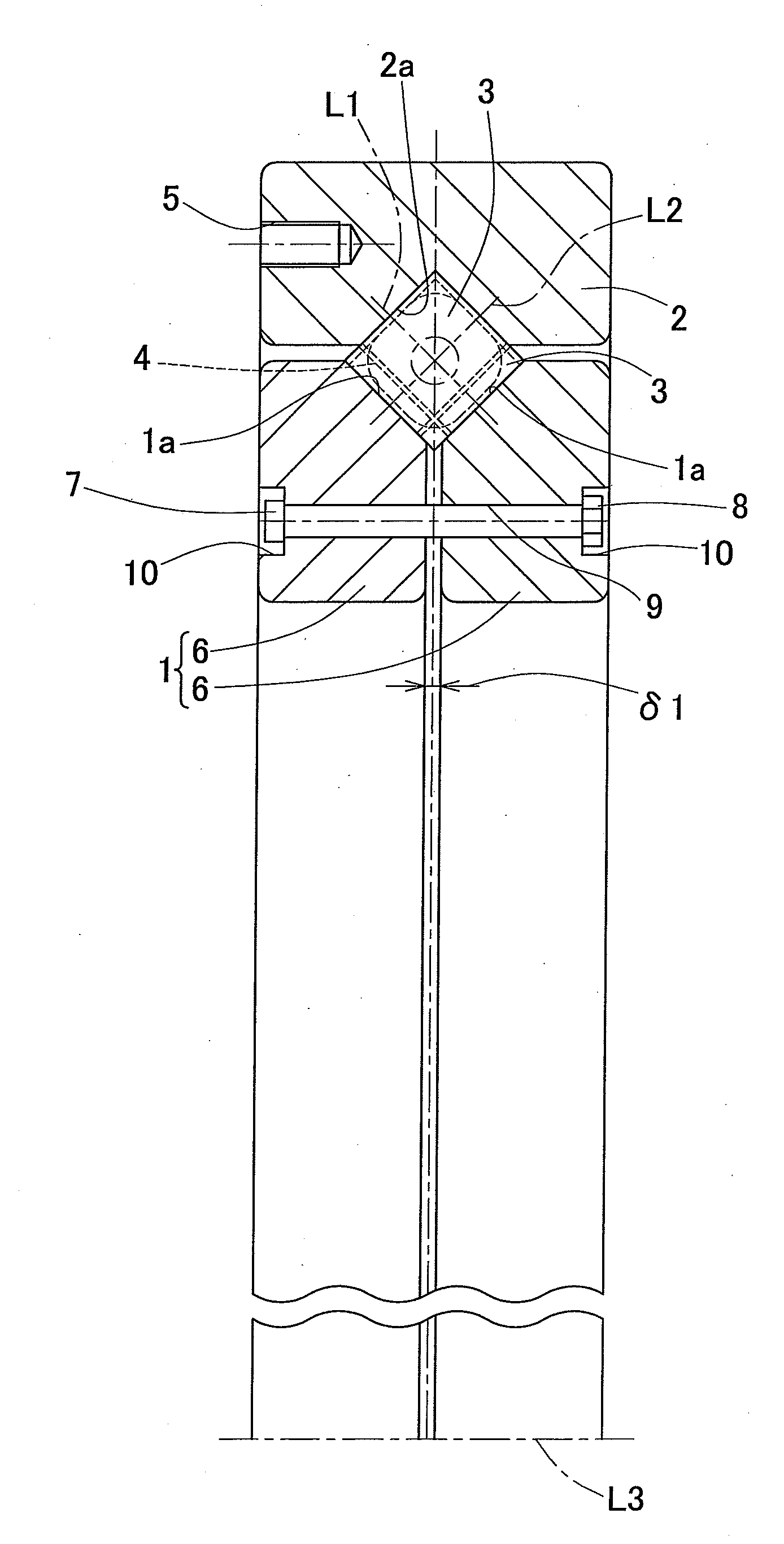
[0043]A wind / tidal power generation bearing according to a first embodiment of the present invention will be described with reference to FIG. 1 to FIGS. 3A, 3B. The wind / tidal power generation bearing according to this embodiment is used as a rolling bearing for supporting a main shaft of a wind power generator or a main shaft of a tidal power generator.

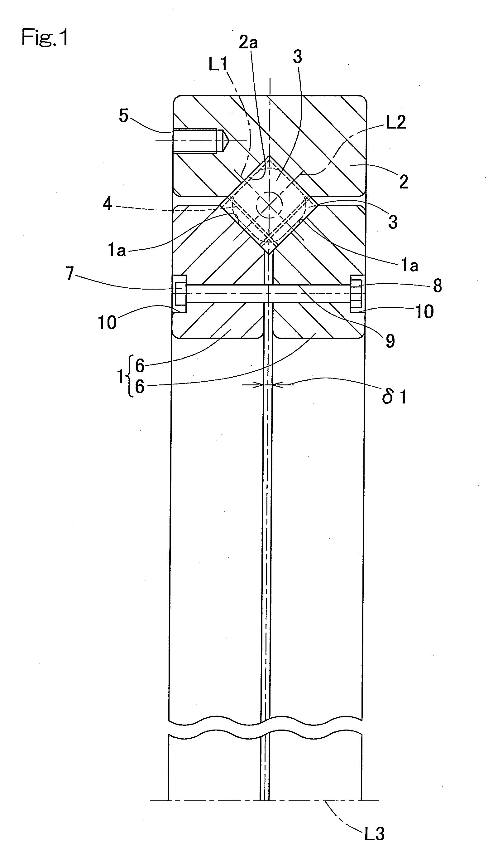
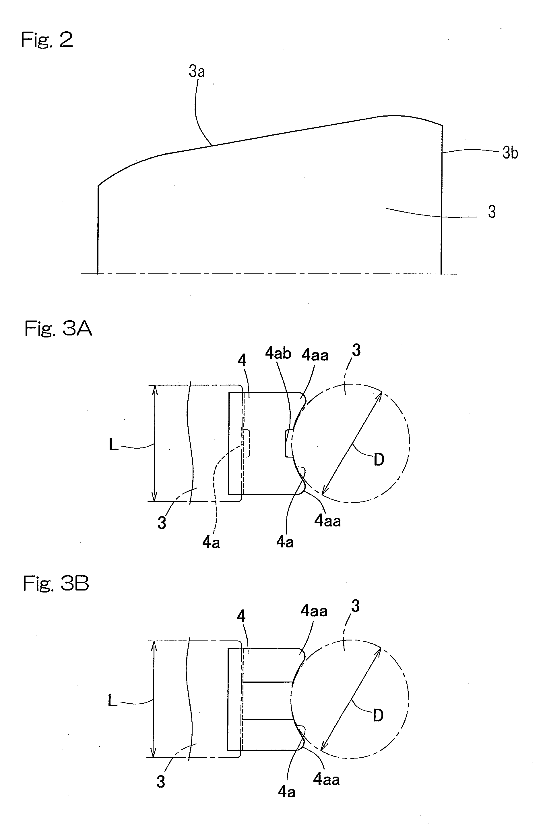
[0044]As shown in FIG. 1, the bearing includes an inner ring 1, an outer ring 2, a plurality of rollers 3 which are rollably disposed between raceway surfaces 1a, 2a of these inner and outer rings 1, 2, and retainers 4 for retaining the respective rollers 3. In the example of FIG. 1, tapered rollers are used as the rollers 3. A bearing space between the inner and outer rings 1, 2 is filled with a lubricant composed of grease. The bearing is a so-called cross tapered bearing which is capable of supporting loads in both directions, that is, a radial load and an axial load, in which the plurality of rollers 3 are arranged in a circumfer...


PUM


Abstract

The wind/tidal power generation bearing for supporting a main shaft of a wind power generator or a main shaft of a tidal power generator includes a rolling bearing including an inner ring, an outer ring and a plurality of rollers disposed between the inner ring and the outer ring. The plurality of rollers are arranged in a circumferential direction such that axes of alternate rollers or alternate sets of a plurality of rollers intersect each other, thereby reducing a bearing width as compared to a double row tapered roller bearing or the like of the conventional art. Therefore, in the wind power generator or the tidal power generator, a space in an axial direction can be saved as compared to the conventional art.

Description

CROSS REFERENCE TO THE RELATED APPLICATION[0001]This application is a continuation application, under 35 U.S.C. §111(a), of international application No. PCT / JP2013 / 074326, filed Sep. 10, 2013, which claims priority to Japanese patent application No. 2012-205228, filed Sep. 19, 2012, the disclosure of which are incorporated by reference in their entirety into this application.BACKGROUND OF THE INVENTION[0002]1. Field of the Invention[0003]The present invention relates to a wind / tidal power generation bearing which supports a main shaft of a wind power generator or a main shaft of a tidal power generator.[0004]2. Description of Related Art[0005]Regarding a bearing for supporting a main shaft of a wind power generator, since an axial load acting on a windmill is applied to the bearing, as a system of supporting the main shaft, a single row cylindrical roller bearing or a self-aligning roller bearing may be used at the blade side, and an inward-facing type double row tapered roller bea...

Claims


Application Information

Patent Timeline
Patent Type & Authority Applications(United States)
IPC IPC(8): F16C33/58F16C19/38F16C33/60F16C33/66F16C33/80
CPCF16C33/585F16C33/6659F16C19/383F16C33/60F16C33/80F16C19/40F16C33/6607F16C33/664F16C19/362F03B13/264F05B2240/50F03B11/06F16C2300/14F03D13/35F16C2360/31Y02E10/20Y02E10/72Y02E10/30
Inventor SHIMIZU, YASUHIRO
Owner NTN CORP
Why Eureka
Try Eureka