Fault detection in brushless exciters

a brushless exciter and fault detection technology, applied in the direction of electric generator control, dynamo-electric converter control, instruments, etc., can solve the problems of increasing the stress on other devices, short circuit, direct fault detection in the rotating rectifier of ac brushless exciter becomes very difficult, etc., to achieve linear but balanced behaviour, high imbalance effect, and rapid rotating diode fault detection respons

Active Publication Date: 2015-07-16
ROLLS ROYCE PLC
View PDF12 Cites 20 Cited by
  • Summary
  • Abstract
  • Description
  • Claims
  • Application Information

AI Technical Summary

Benefits of technology

[0030]In particular, the present invention provides a rapid rotating diode fault detection response by focussing on acquiring measurement data from the exciter armature winding. The exciter armature winding is directly coupled, electrically, with the rotating rectifier. Whereas the exciter field winding, which is used widely in the prior art to try to detect rotating diode faults, is not directly coupled, electrically, with the rotating rectifier. Under normally balanced operating conditions, i.e. in the absence of rotating diode faults, the exciter armature winding shows highly linear but balanced behaviours. Thus, any diode fault will upset the exciter armature winding balanced behaviour immediately. For example, the exciter armature winding exhibits highly imbalanced effects due to the loss of rectification at the main field winding. Thus, the reflected harmonics due to armature reaction effects are “seen” directly at the exciter armature winding, while exciter field winding will require more time to “see” the effects. Hence,

Problems solved by technology

Short circuit failure
The failures could be single-diode failure or multiple-diodes failure, and each could be either short circuit or open circuit fault.
Having removed the need for brushes, commutator and slip rings, direct fault detection in the rotating rectifier in AC brushless exciter becomes very challenging.
In this case, the field current increases stress on other devices and also reduce the transient capability of the machine.
However, this increases stresses on the other diodes and could lead to further diode failures.
Moreover, the voltage regulator could be damaged due to increased excitation.
A diode short circuit is the most frequent failure condition.
During diode short circuit, the output of the exciter is severely affected and the main alternator is unable to provide rated voltage without overloading the exciter.
Furthermore, a shorted diode is one of the most severe fault conditions, which requires a very large increase in exciter's field current to maintain the a

Method used


Image

  • Fault detection in brushless exciters
  • Fault detection in brushless exciters
  • Fault detection in brushless exciters

Examples


first embodiment

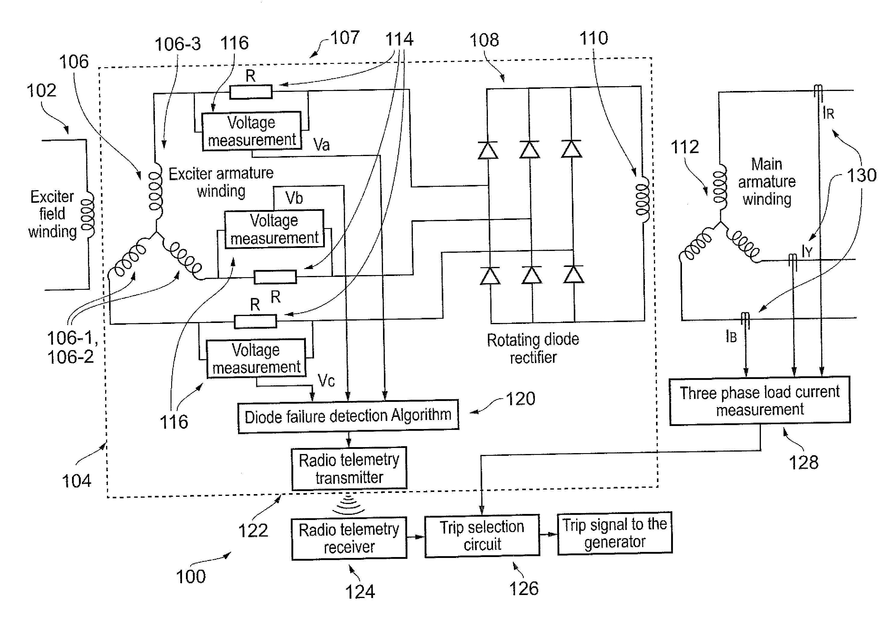
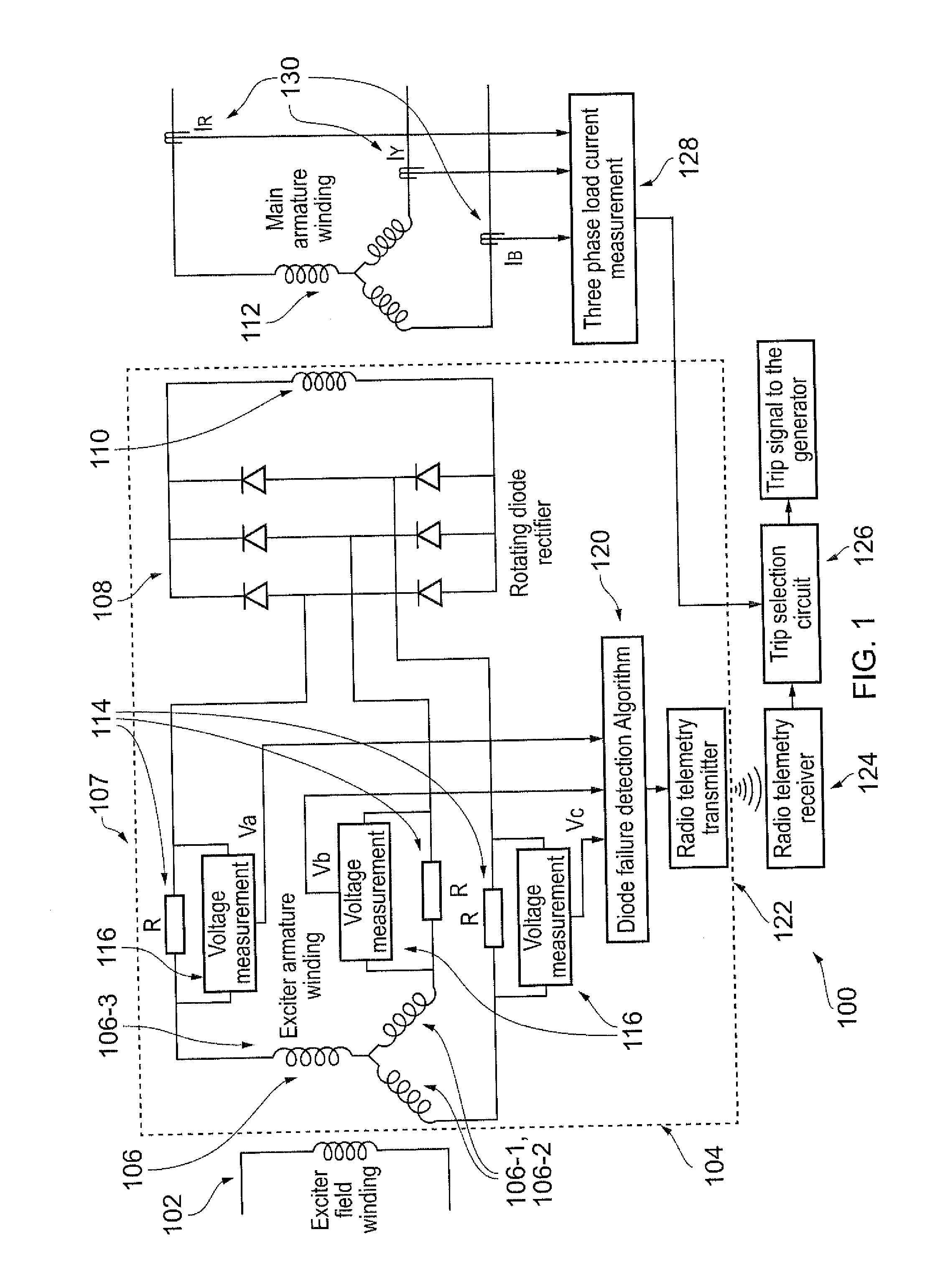
[0094]FIG. 1 shows the present invention applied to a brushless synchronous generator 100, as described above.

[0095]A respective small resistor 114 is connected in series with each armature (phase) of exciter armature winding, as shown. The measured voltage drop across each resistor, e.g. measured by respective voltage sensors 116, is used to derive an exciter fault (failure) indication signal based upon the algorithm / methodology proposed herein. In particular, the exciter fault (failure) may be a rotating diode fault (failure).

[0096]In embodiments, the acquired data (the measured voltage drops) are processed according to the proposed algorithm / methodology, e.g. by a processor 120, and a final control signal is optionally transferred to the stator through a rotating radio telemetry transmitter 122 in order to control the operation of the generator.

[0097]For example, a stationary receiver 124 can optionally be used to collect the control signal from the rotor transmitter. The receive...

third embodiment

[0127]In this third embodiment, in order to detect the fault, e.g. the open or short circuit diode fault, the currents (Ia, Ib and Ic) in the respective exciter armatures 106-1, 106-2 and 106-3 are analysed with reference to a threshold value.

[0128]So, for example, S301 may be similar to S201. However in S302, the armature currents Ia, Ib and Ic are calculated, for example using the following equations: Ia=Va / R, Ib=Vb / R and Ic=Vc / R.

[0129]In S303 harmonic analysis of the armature currents is performed, for example as discussed below in more detail.

[0130]In S304 the result of the harmonic analysis is compared with a (predefined) threshold value, similarly to that described for S203 above to establish whether or not a fault has occurred.

[0131]In the event that a determination is made that the result of S303 does not exceed the (predefined) threshold, then in S305 a judgement may be made that there is no fault in the exciter circuit 107; specifically that there is no fault in a rotating...

fourth embodiment

[0137]FIG. 8 shows the present invention, in which respective current sensors 132 are arranged to measure the current flowing in each armature.

[0138]Through harmonic analysis (similar to that of the third embodiment and as described below) of the measured exciter armature currents, the open circuit or short circuit diode fault can be detected.

[0139]An example of the harmonic analysis will be discussed below in more detail.

[0140]In a fifth embodiment, three voltage sensors 116 are used to measure the respective voltages of each exciter armature 106-1, 106-2 and 106-3, similarly to the second embodiment. Two self-powered current sensors 132 are also used to measure the line currents of two of three exciter armatures, e.g. as shown in FIG. 9. Current sensors 132 may be similar to those shown in FIG. 8 for example.

[0141]Computational unit 120 (equivalent to processor 120) is provided to perform the algorithm / methodology for determining whether or not exciter circuit 108, specifically re...


PUM


Abstract

A method for detecting a fault in an exciter circuit, suitable for use in a brushless generator, the exciter circuit including (a) an exciter armature winding, having a plurality of armatures, arranged to generate a multiphase AC signal, each armature of the plurality of armatures providing a respective sub-signal component of the multiphase AC signal, and (b) a rectifier circuit for receiving the sub-signals via the respective armatures, the rectifier circuit comprising a plurality of components arranged to rectify the sub-signals to provide a rectified output signal, wherein the method includes the steps of: acquiring a respective operational sub-value for a first characteristic of each of at least two of the respective sub-signals; deriving an operational value indicative of a relationship between the acquired respective operational sub-values; determining whether a fault has occurred in the exciter circuit on the basis of the derived operational value.

Description

FIELD OF THE INVENTION[0001]The present invention relates to the detection of faults in brushless exciters, for example exciters in brushless synchronous generators; in particular, but not exclusively, to the detection of rectifier diode faults in exciters.BACKGROUND OF THE INVENTION[0002]The brushless synchronous generator (BLSG) is widely used in aircraft and marine vessels for onboard power generation and it is also used as a shaft generator in energy efficient hybrid propulsion systems for marine vessels. The brushless excitation offers increased reliability and reduced maintenance requirements for the generator.[0003]The exciter is a key component of a generator and the generator's output voltage is regulated by controlling the exciter's field current. The main function of the excitation system is to provide variable DC current to excite the main magnetic field in the rotor. Furthermore, it supports short time overload capability, controlling the terminal voltage with suitable ...

Claims


Application Information

Patent Timeline
IPC IPC(8): G01R31/34
CPCG01R31/343H02H7/065H02P9/00H02P9/102H02P11/00
Inventor VISWANATHAN, VAIYAPURIGAJANAYAKE, CHANDANAGUPTA, AMITNADARAJAN, SIVAKUMAR
Owner ROLLS ROYCE PLC
Why Eureka
Try Eureka