
Diesel oxidation catalyst and exhaust system

a diesel engine and oxidation catalyst technology, applied in metal/metal-oxide/metal-hydroxide catalysts, machines/engines, arsenic compounds, etc., can solve the problems of low cost of palladium, high cost of palladium and platinum, and high cost of platinum, so as to improve catalyst durability and reduce the relative cost of palladium to platinum

Active Publication Date: 2015-07-23
JOHNSON MATTHEY PLC
View PDF4 Cites 11 Cited by
  • Summary
  • Abstract
  • Description
  • Claims
  • Application Information

AI Technical Summary

Benefits of technology

The invention relates to an oxidation catalyst for reducing emissions in exhaust gas from compression ignition engines. The catalyst includes a combination of manganese and platinum, which have low temperature activity for oxidizing carbon monoxide, hydrocarbons, and nitric oxide. It is effective in converting high levels of CO, particularly at temperatures below 250°C, and also has good activity towards HCs. The catalyst can be used in conjunction with other emissions control devices in an exhaust system, and the NO oxidation activity can be improved by the inclusion of a reduced amount of expensive platinum. The catalyst can also provide a stable NO oxidation activity over its lifetime.

Problems solved by technology

Even though, in general, the cost of palladium has historically been lower than that of platinum, both palladium and platinum are expensive metals.
Platinum is expensive and is often included in oxidation catalysts in relatively large amounts for, amongst other things, its oxidation activity toward NO.

Method used


Image

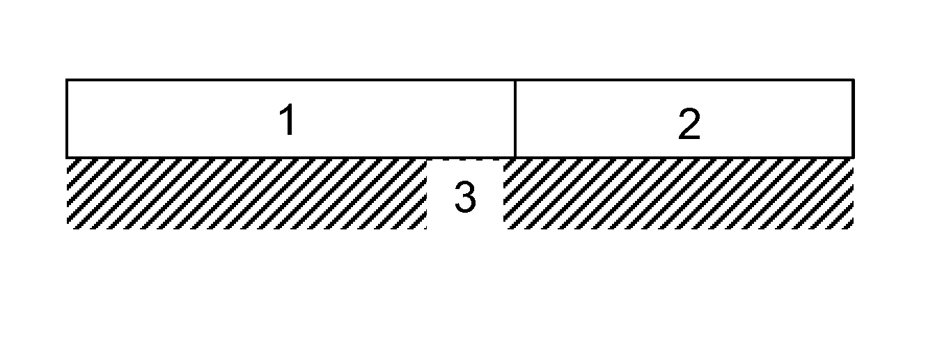
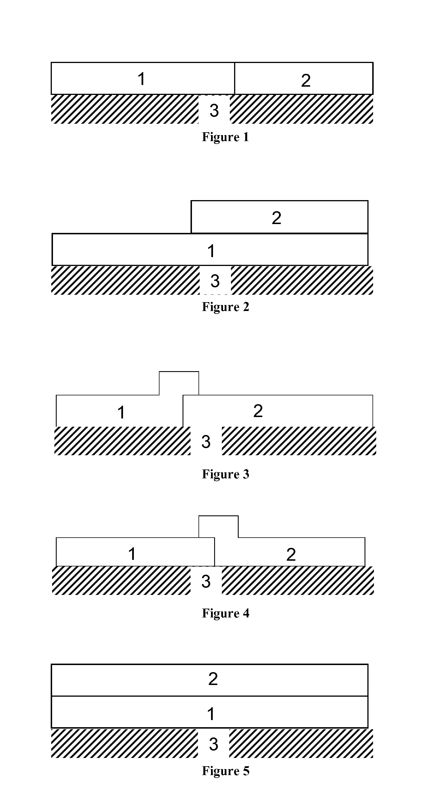
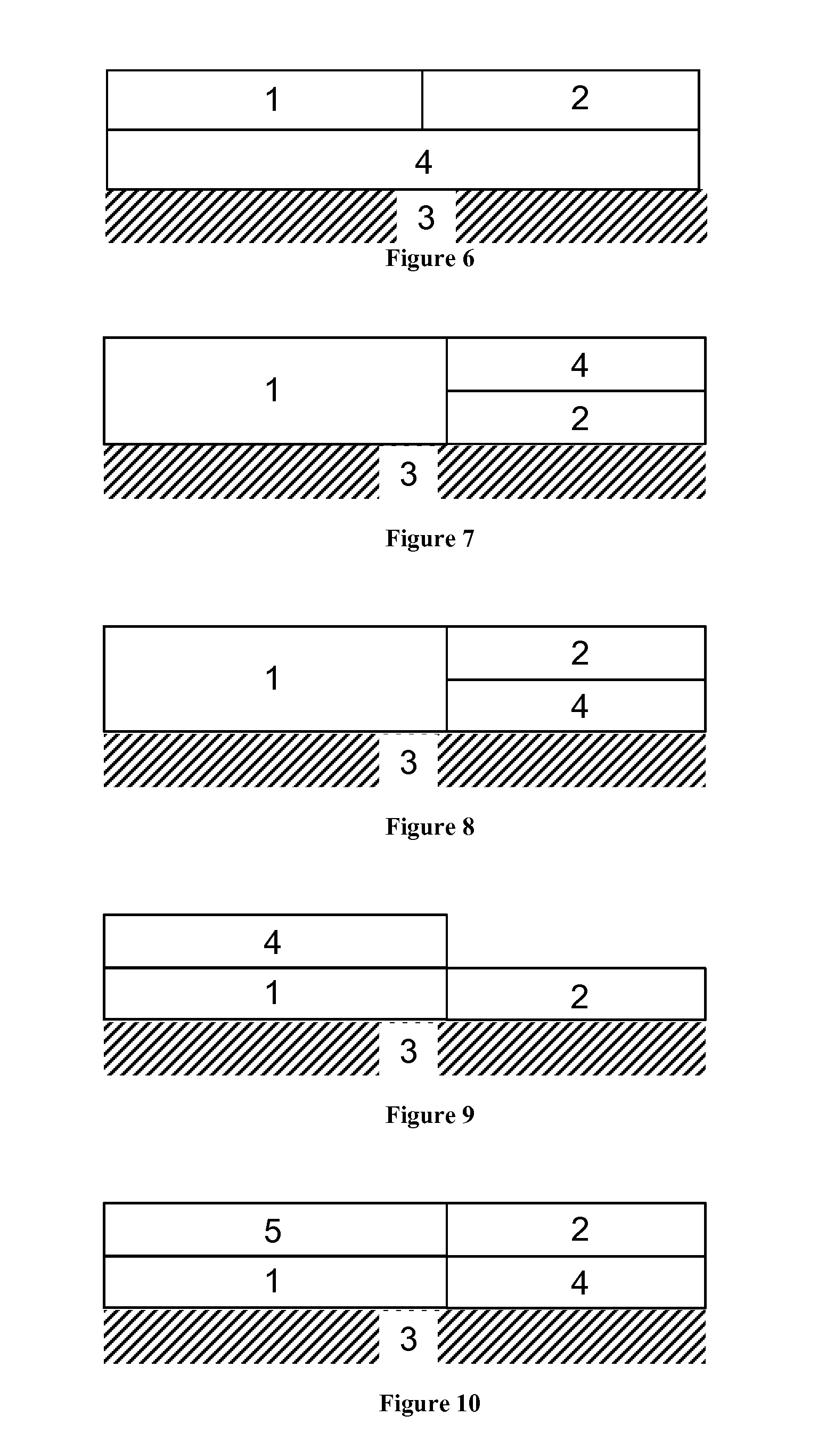
  • Diesel oxidation catalyst and exhaust system
  • Diesel oxidation catalyst and exhaust system
  • Diesel oxidation catalyst and exhaust system

Examples


example 1

[0280]A first slurry was prepared as follows: silica-alumina powder was slurried in water and milled to a d90 <20 micron. Soluble platinum salt was added followed by manganese nitrate. The mixture was stirred to homogenise.

[0281]The slurry was applied to the outlet end of a cordierite flow through monolith having 400 cells per square inch using established coating techniques. It was then dried and calcined at 500° C. The Pt loading on the part was 15 g ft−3. The manganese loading on the part was 50 g ft−3.

[0282]A second slurry was prepared by taking silica-alumina powder and milling to a d90 −3 and a Pd loading of 15 g ft−3.

example 2

[0283]A first slurry was prepared and applied to a cordierite flow through monolith having 400 cells per square using the same methods of Example 1. The Pt loading on the part was 15 g ft−3. The manganese loading on the part was 50 g ft−3.

[0284]A second slurry was prepared by taking silica-alumina powder and milling to a d90−3 and manganese loading of 100 g ft−3.

Experimental Results

Measurement of Oxidation Activity

[0285]Core samples were taken from each of the catalysts of Examples 1 and 2. The cores were hydrothermally “aged” in an oven at 750° C. for 15 hours using 10% water. Catalytic activity was determined using a synthetic gas bench test. The cores were tested in a simulated catalyst activity testing (SCAT) gas apparatus using the inlet gas mixture in Table 1. In each case the balance is nitrogen. The oxidation activity for CO and HC is determined by the light off temperature whereby 50% conversion is achieved (T50). The oxidation activity for NO is determined as the percentag...

example 3

[0288]Silica-alumina powder was slurried in water and milled to a d90 −3. The ratio of Pt:Pd was 4:1 by mass.


PUM

PropertyMeasurementUnit
temperature oxidation activityaaaaaaaaaa
molar ratioaaaaaaaaaa

Abstract

An oxidation catalyst for treating an exhaust gas from a diesel engine, which oxidation catalyst comprises: a first washcoat region comprising platinum (Pt), manganese (Mn) and a first support material; a second washcoat region comprising a platinum group metal (PGM) and a second support material; and a substrate having an inlet end and an outlet end; wherein the second washcoat region is arranged to contact the exhaust gas at the outlet end of the substrate and after contact of the exhaust gas with the first washcoat region.

Description

CROSS REFERENCE TO RELATED APPLICATIONS[0001]This application claims priority benefit to Great Britain Patent Application No. 1401115.9 filed on Jan. 23, 2014, and to Great Britain Patent Application No. 1405871.3 filed on Apr. 1, 2014, all of which are incorporated herein by reference.FIELD OF THE INVENTION[0002]The invention relates to an oxidation catalyst for a diesel engine and to an exhaust system for a diesel engine comprising the oxidation catalyst. The invention also relates to methods and uses of the oxidation catalyst for treating an exhaust gas from a diesel engine.BACKGROUND TO THE INVENTION[0003]Diesel engines produce an exhaust emission that generally contains at least four classes of pollutant that are legislated against by inter-governmental organisations throughout the world: carbon monoxide (CO), unburned hydrocarbons (HCs), oxides of nitrogen (NOx) and particulate matter (PM). Emissions standards for diesel engines, whether stationary or mobile (e.g. vehicular di...

Claims


Application Information

Patent Timeline
Patent Type & Authority Applications(United States)
IPC IPC(8): B01J35/04B01J29/70B01D53/94B01J23/656
CPCB01J35/04B01J23/6562B01J29/7015B01J29/7007B01D53/945B01D53/9454B01D2255/30B01D2255/502B01D2255/2073B01D2255/1023B01D2255/1021B01D2255/2092B01D2255/50B01J37/0244B01J37/0246F01N3/2828B01D2255/504B01J37/0234B01J37/10B01J29/7415B01J29/743B01J37/0036B01D2255/2065B01D2255/20707B01D2255/20715B01D2255/20776B01D2255/40B01D2255/9022B01D2255/9032B01D2257/404B01D2257/502B01D2257/702F01N3/103F01N3/106F01N3/281F01N3/035F01N2330/02F01N2330/06F01N2510/06F01N2510/0682F01N2510/0684B01J23/66B01J37/0228B01J23/34B01J23/38B01D53/56B01J23/42B01D53/62B01J23/44B01D53/72B01J23/58B01J23/63B01D53/922B01D53/9459B01D53/9468B01J29/40F01N3/2882B01D2201/62B01D2255/902B01D2255/903B01D2255/91B01D2255/912F01N2570/10F01N2570/12F01N2570/14B01D53/9472B01D53/944Y02C20/10Y02A50/20Y02T10/12B01J35/19B01J35/56B01J35/40B01D53/94B01D53/9413B01D53/9427F01N3/0814B01D53/9418B01D53/9422F01N3/10B01D53/9445B01J21/10B01J23/02B01J23/40B01J23/656F01N3/0807F01N3/0835F01N3/0842F01N3/0857B01J21/12B01J37/02B01D53/92B01J35/00F01N3/28F01N3/022B01J29/70B01D53/9477B01J23/10B01D2255/2042B01J37/0219B01J37/0236B01J37/086F01N2370/02
Inventor CHIFFEY, ANDREW FRANCISGOODWIN, JOHN BENJAMINLEELAND, JAMESMOREAU, FRANCOIS
Owner JOHNSON MATTHEY PLC
Learn More