
Arrangement of a photobioreactor or a microbiological reactor

a microbioreactor and photobioreactor technology, applied in the field of biochemical processes, can solve the problems of inefficient reaction, lack of heat transfer unit, and relatively low production rate of reaction product, and achieve the effects of enhancing the reaction rate, enhancing the photochemical reaction rate, and enhancing the mixing of reaction fluid

Inactive Publication Date: 2015-07-30
PHOTANOL
View PDF5 Cites 14 Cited by
  • Summary
  • Abstract
  • Description
  • Claims
  • Application Information

AI Technical Summary

Benefits of technology

The invention provides a way to improve the reaction process in a tank by using heat pipes and light units. This leads to a higher efficiency of the reaction process and more production of the desired product. In addition, the invention includes a second means for distributing a gas that prevents the growth of phototrophic organisms on the illumination devices. This ensures the continuous operation of the reaction process.

Problems solved by technology

The photo-bioreactor according to the prior art does not provide any heat transfer unit that can help to control the temperature inside the volume.
Under these circumstances, the reaction inside the volume will be affected and the result will be an inefficient reaction and possibly a relatively low production rate for the reaction product.
On the contrary, the prior art does not allow the arrangement of a heat transfer unit without compromising the efficiency and the result of the photo-bio reaction.
A disadvantage of these types of heat transfer units is that an inhomogeneous heat distribution in the volume may be created, which may result into an irregular reaction (and / or reaction rate) in the volume.
By having this type of heat transfer distribution, some parts of the reactor can be overheated, which may cause malfunction of (parts of) the reactor.
Moreover, other disadvantages of the tubular systems relate to relatively high volume occupancy, relatively high demand for illumination and thus relatively high energy consumption, cleaning problems and low efficiency in terms of mass production per unit of volume.

Method used


Image

  • Arrangement of a photobioreactor or a microbiological reactor
  • Arrangement of a photobioreactor or a microbiological reactor
  • Arrangement of a photobioreactor or a microbiological reactor

Examples


embodiment 1

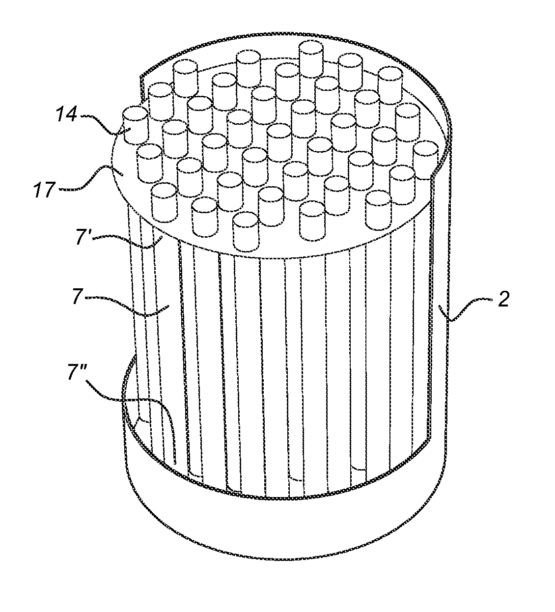
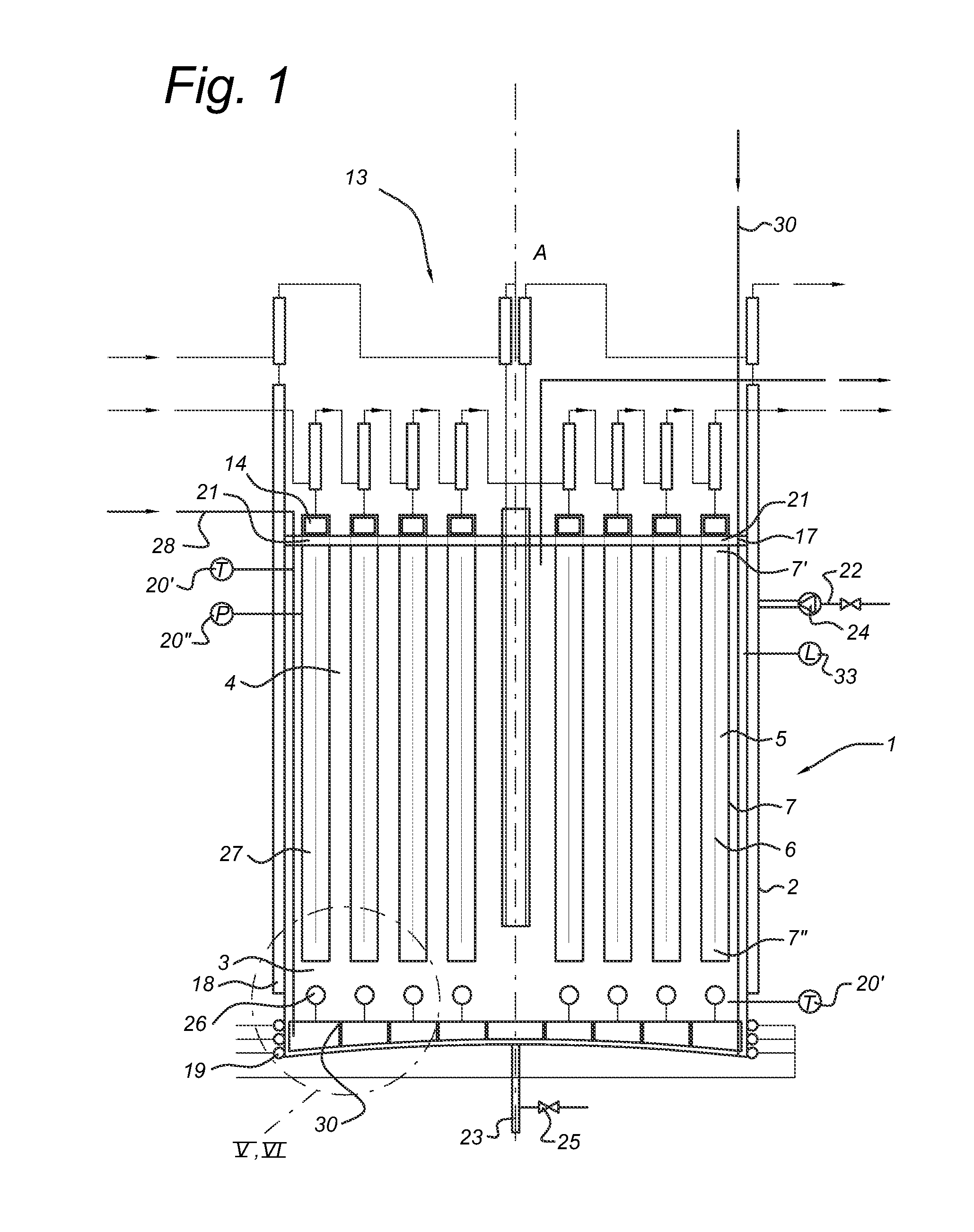
[0104]A reactor for biochemical and / or photochemical processes comprising:

[0105]a tank having a volume for containing a reaction fluid,

[0106]a heat transfer unit being arranged in the volume,

[0107]a plurality of light units arranged in the volume of the tank,

[0108]wherein the heat transfer unit comprises a plurality of heat pipes, and the light units are mounted on the plurality of heat pipes.

embodiment 2

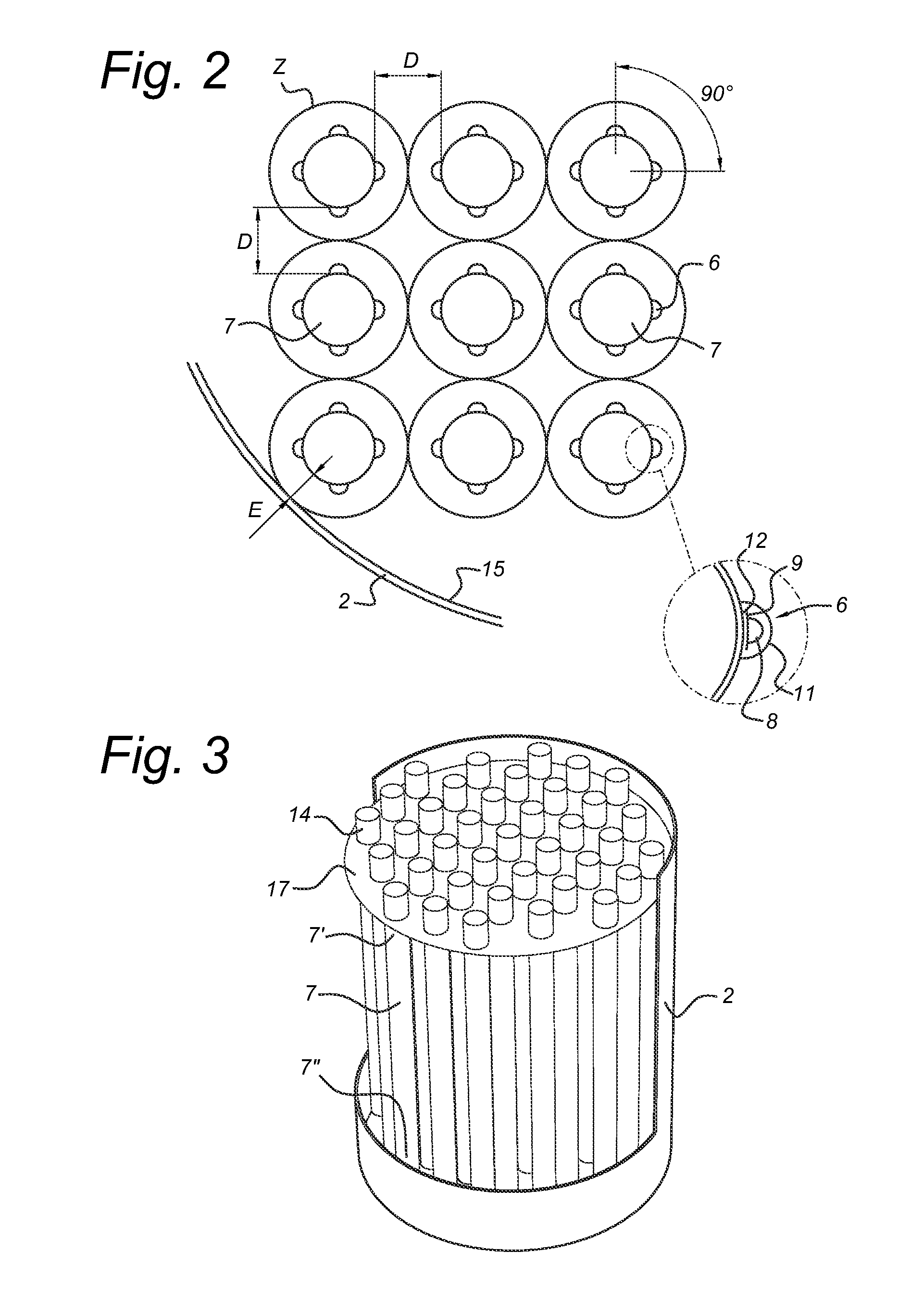
[0109]The reactor according to embodiment 1, wherein the plurality of heat pipes are vertically positioned, with respect to the longitudinal axis of the tank, in a regular arrangement such that the distance between the longitudinal axis of heat pipes in each closest neighboring pair of heat pipes is constant.

embodiment 3

[0110]The reactor according to any one of the embodiments 1 or 2, wherein the light units comprise a plurality of light emitting diodes (LED) mounted on a printed circuit board, the printed circuit board being mounted on the heat pipe surface.


PUM

PropertyMeasurementUnit
wavelength rangeaaaaaaaaaa
volumeaaaaaaaaaa
distanceaaaaaaaaaa

Abstract

A reactor for biochemical and / or photochemical processes includes a tank having a volume for containing a reaction fluid, a heat transfer unit being arranged in the volume, a plurality of light units arranged in the volume of the tank. The heat transfer unit includes a plurality of heat pipes. The light units are mounted on the plurality of heat pipes.

Description

FIELD OF THE INVENTION[0001]The present invention relates to a reactor for biochemical processes comprising a tank having a volume for containing a reaction fluid, a heat transfer unit being arranged in the volume, a plurality of light units arranged in the volume of the tank. Moreover, the present invention also relates to the use of the reactor.BACKGROUND OF THE INVENTION[0002]In general, a reactor for biochemical processes having a tank for containing a fluid, with a heat transfer unit and lights arranged in the volume of the tank are known in the art.[0003]In particular, photo-bioreactors are known that contain a reaction fluid in a form of an aqueous solution with phototrophic microorganisms that are cultivated by utilizing light energy. These organisms use the process of photosynthesis to build their own biomass from light, water and carbon dioxide (CO2). In a similar manner in microbiological reactors a fluid containing microorganisms, often obtained after selected molecular ...

Claims


Application Information

Patent Timeline
Patent Type & Authority Applications(United States)
IPC IPC(8): C12M1/00C12M1/02C12M1/34C12N1/12C12M1/36
CPCC12M21/02C12N1/12C12M31/10C12M41/18C12M41/40C12M41/06C12M41/48C12M41/24
Inventor HELLINGWERF, KLAAS JANVAN LIESHOUT, THEOKOBLENS, PAULVAN GRONDELLE, WILMARVAN ALPHEN, PASCAL
Owner PHOTANOL
Learn More