
Electroplating cell, and metal coating and method of forming the same

a technology of electroplating cell and metal coating, which is applied in the direction of electrolysis components, electrolysis apparatus and processes, transportation and packaging, etc., can solve the problems of high cost of plating solution management and waste liquid treatment, high cost of film forming speed, and need for vacuum units, so as to achieve excellent metal coating, reduce electrodeposition efficiency, and reduce the effect of electrodeposition efficiency

Active Publication Date: 2015-08-06
TOYOTA JIDOSHA KK
View PDF3 Cites 6 Cited by
  • Summary
  • Abstract
  • Description
  • Claims
  • Application Information

AI Technical Summary

Benefits of technology

The invention provides an electroplating cell that can easily form a metal coating and prevent the formation of a high bath voltage caused by additives in the plating solution. By adding the organic plating additive to the separator, the additive can be gradually moved to the cathode chamber solution, resulting in a high quality metal coating with improved properties. This method also allows for a reduction in the amount of additive needed, which decreases the input cost. Additionally, the risk of a large amount of additive causing a decrease in electrodeposition efficiency or complicated concentration control is minimized.

Problems solved by technology

However, in this technique, a mask forming step and a mask removing step are required, and there is a problem in that the cost for the management and waste liquid treatment of a plating solution is high.
However, in this method of physically forming a metal coating, a film forming speed is generally slow, and a vacuum unit is necessary.
Therefore, it is difficult to say that a system using this method is an economical high-speed production system.
However, with this “printing method”, it is difficult to form a circuit having low volume resistivity even if a volatile or sublimable binder is used.
Therefore, a higher cost is required.
In particular, it is difficult to electrodeposit metal (for example, metal in which deposition potential of nickel ions, zinc ions, tin ions, or the like is low), in which an electrodeposition reaction (reduction deposition reaction) competes with a H+ ion discharge reaction (hydrogen evolution reaction), from an acidic or slightly acidic aqueous solution having high H+ concentration using a separator.
Further, since the organic additive is decomposed and consumed on an electrode, it is also necessary to remove a waste product.
In addition, when a large amount of the organic additive is added to the plating bath, there is a problem in that electrodeposition efficiency is likely to decrease.
Furthermore, when the separator is an ion exchange membrane, and when the organic additive is an ionic compound, there is a problem in that the organic additive is adsorbed onto the separator, conductivity decreases, and bath voltage increases.

Method used

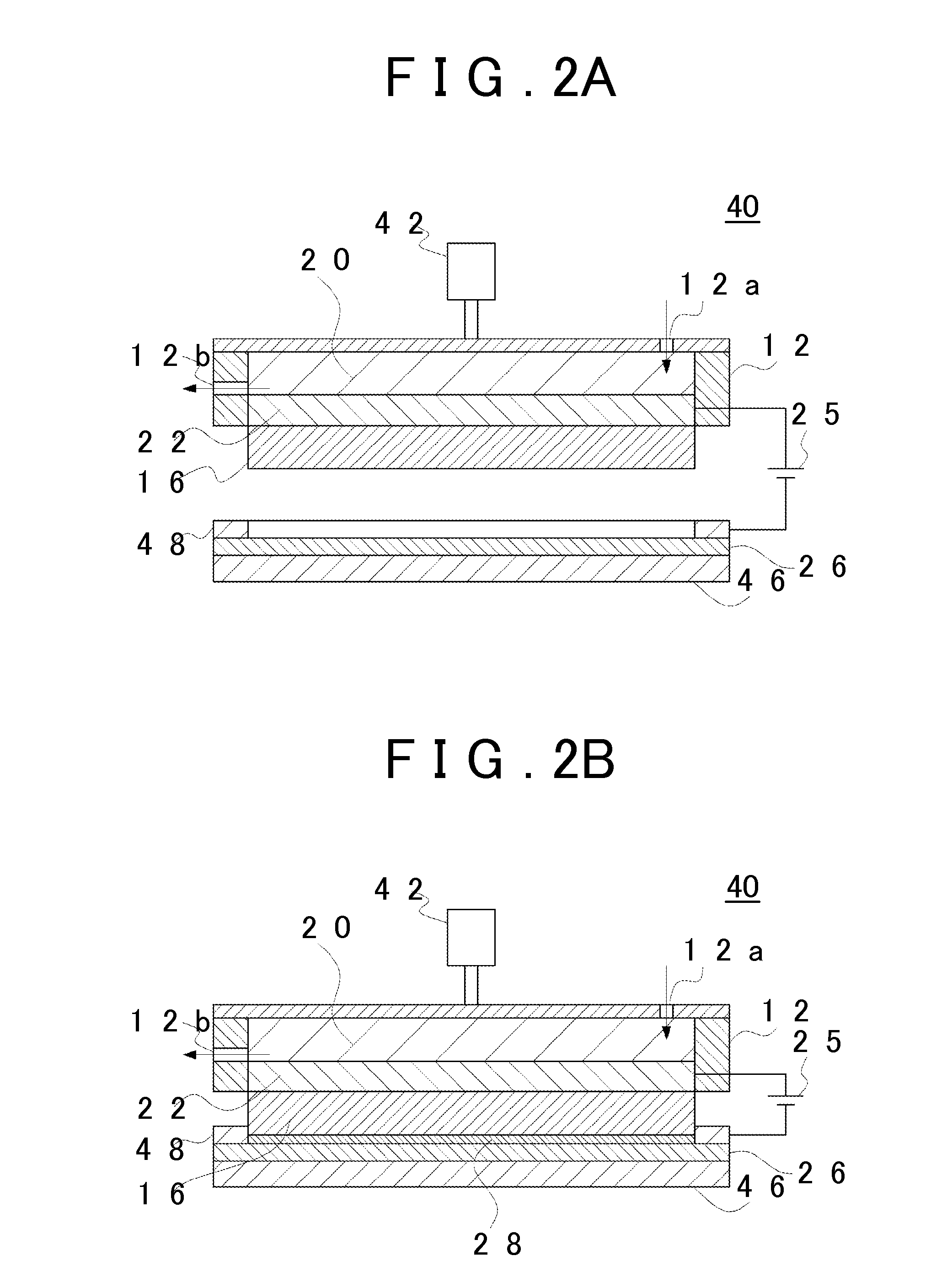

Image

  • Electroplating cell, and metal coating and method of forming the same
  • Electroplating cell, and metal coating and method of forming the same
  • Electroplating cell, and metal coating and method of forming the same

Examples


examples 1 and 2

1.1. Examples 1 and 2

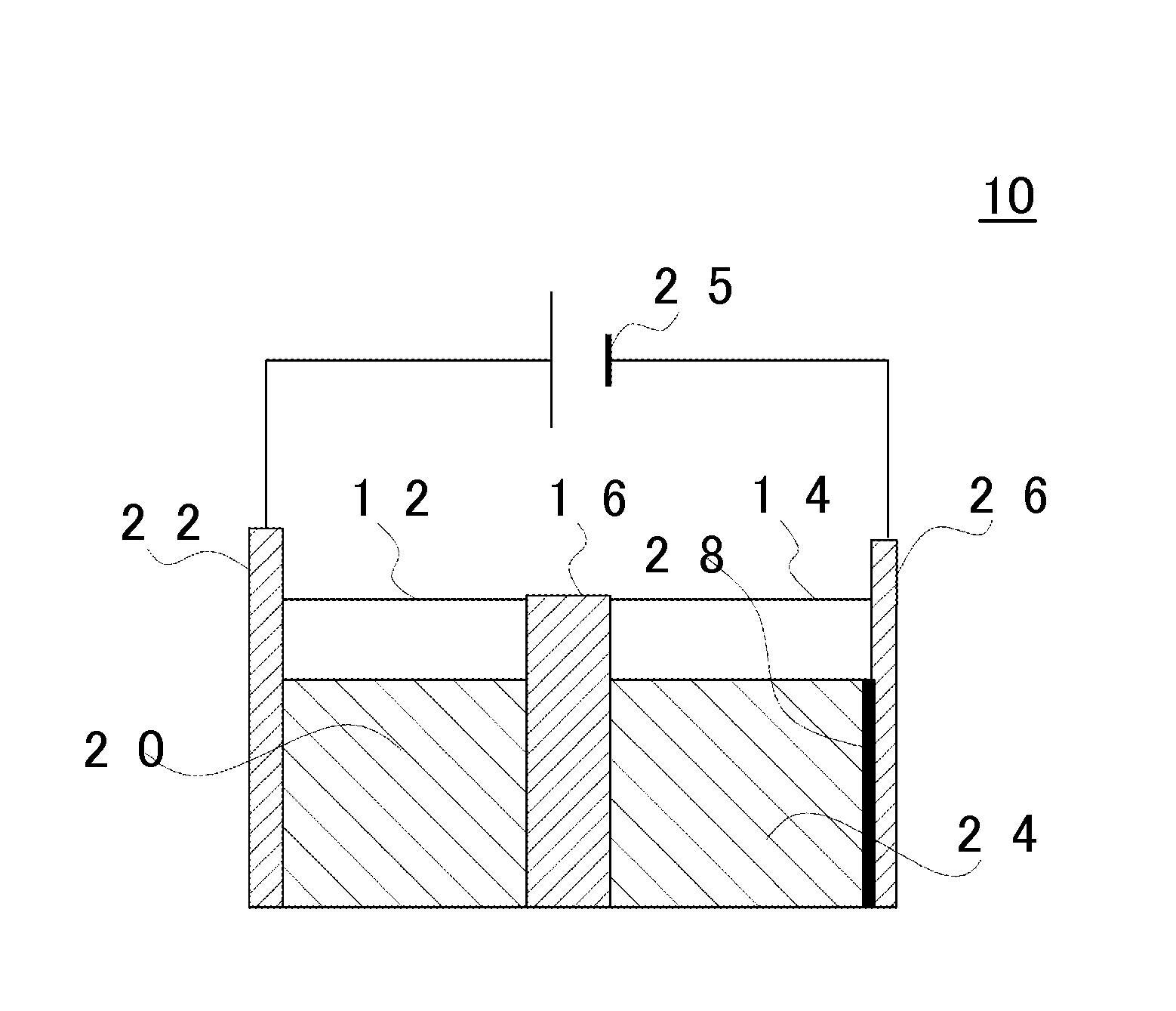
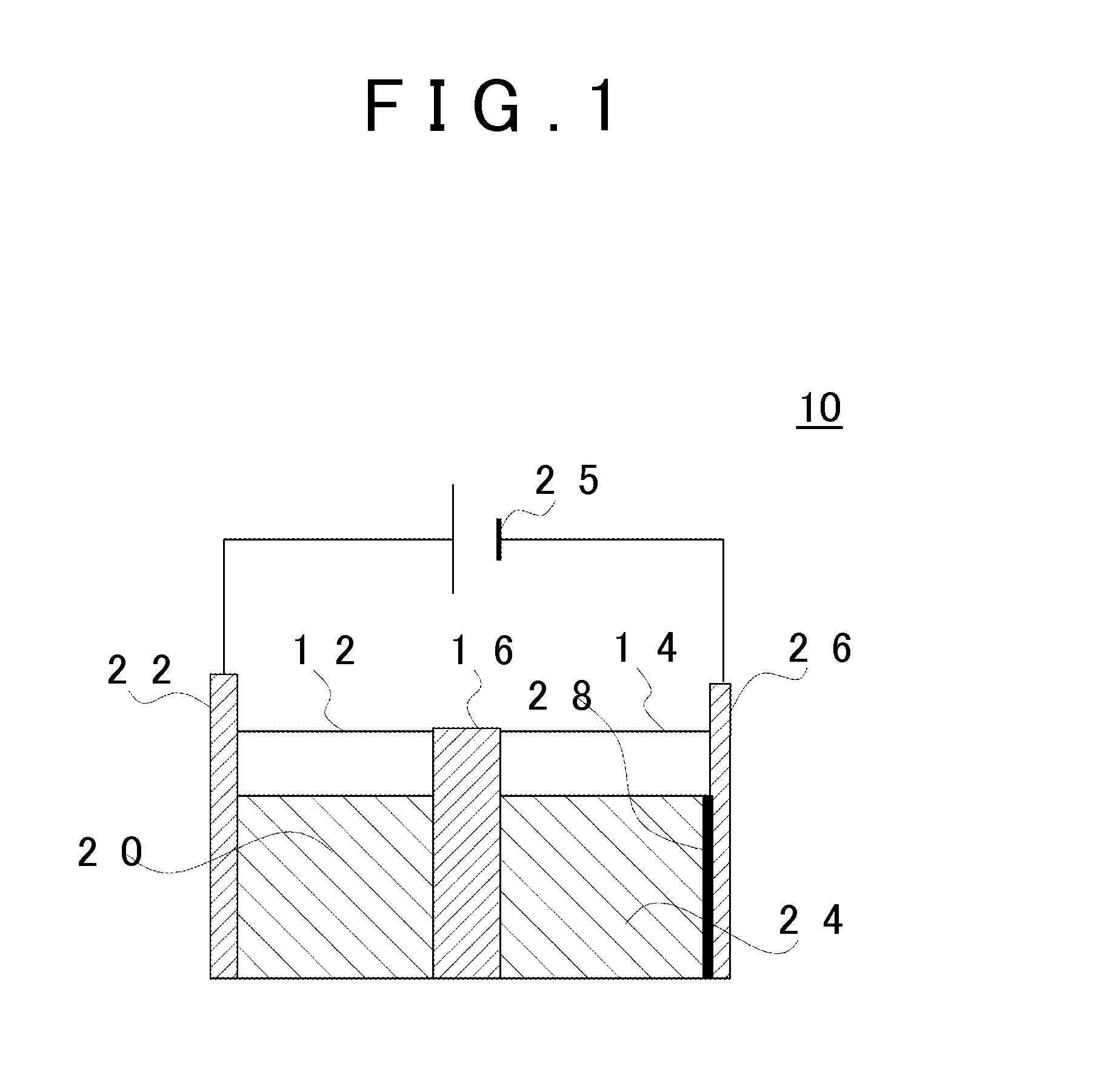
[0187]The metal coating 28 was prepared using the electroplating cell 10 illustrated in FIG. 1. As the base material of the separator 16, a perfluorosulfonic acid-based cation exchange membrane (thickness: 183 μm, size: 30 mm×30 mm) was used. As the solution for fixing the additive to the separator 16, 100 mL of an aqueous solution in which hexadecyltrimethylammonium bromide or tetramethylammonium hydroxide is dissolved in ultrapure water was prepared. The additive concentration in the solution was controlled to be 20% to 100% with respect to the ion exchange capacity of the cation exchange membrane. For ion exchange of the membrane, a dipping treatment was performed using a covered PFA container at 80° C. for 2 hours. In addition, after the ion exchange, the separator 16 was washed with warm water at 80° C. for 2 hours and was held in ultrapure water.

[0188]As the anode 22 and the cathode 26 (sample electrode), a Pt plate having a size of 2 cm×2 cm and a thickne...


PUM

PropertyMeasurementUnit
Fractionaaaaaaaaaa
Fractionaaaaaaaaaa
Fractionaaaaaaaaaa

Abstract

An electroplating cell includes: (i) an anode chamber in which an anode chamber solution is stored; and (ii) a separator that includes a base material and an organic plating additive contained in the base material, separates the anode chamber and a cathode from each other, and selectively allows permeation of metal ions contained in the anode chamber solution.

Description

INCORPORATION BY REFERENCE[0001]The disclosure of Japanese Patent Application No. 2014-019018 filed on Feb. 4, 2014 including the specification, drawings and abstract is incorporated herein by reference in its entirety.BACKGROUND OF THE INVENTION[0002]1. Field of the Invention[0003]The present invention relates to an electroplating cell, and a metal coating and a method of forming the same, and more specifically relates to an electroplating cell which is capable of easily forming a metal coating on a surface of a cathode (plated object), a metal coating which is formed using the electroplating cell, and a method of forming the metal coating.[0004]2. Description of Related Art[0005]A technique of forming a pattern formed of a metal coating (hereinafter, referred to as “metal pattern”) on a conductive substrate with a simple method is required. A technique of masking a portion other than a metal pattern to perform wet electroplating is most commonly used. However, in this technique, a...

Claims


Application Information

Patent Timeline
IPC IPC(8): C25D3/12C25D17/00
CPCC25D3/12C25D21/14C25D5/06C25D17/002Y10T428/12875C25D3/02
Inventor MIURA, FUSAYOSHIMURASE, ATSUSHIHASEGAWA, NAOKIHIRAOKA, MOTOKISATO, YUKI
Owner TOYOTA JIDOSHA KK
Learn More