Passivation of Micro-Discontinuous Chromium Deposited From a Trivalent Electrolyte

a technology of trivalent electrolyte and micro-discontinuous chromium, which is applied in the direction of electrolytic inorganic material coating, electrolysis apparatus and processes, transportation and packaging, etc., can solve the problems of chromic acid being extremely corrosive and toxic, affecting the appearance of the deposit, and reducing the effect of corrosion protection

Active Publication Date: 2015-09-10
MACDERMID ACUMEN INC
View PDF7 Cites 14 Cited by
  • Summary
  • Abstract
  • Description
  • Claims
  • Application Information

AI Technical Summary

Benefits of technology

[0012]It is an object of the present invention to provide imp

Problems solved by technology

Because the chromium deposit is very thin, it tends to have discontinuities through which the underlying nickel is exposed.
This leads to the formation of an electrochemical cell in which the chromium deposit is the cathode and the underlying nickel layer is the anode and thus corrodes.
The net result is that the pores through which the corrosion occurs tend to accumulate deposits of nickel hydroxide, which detract from the appearance of the deposit.
Electrodeposited chromium as produced from a chromic acid electrolyte is a very poor substrate for hydrogen liberation and thus the cathodic reaction is kinetically inhibited and is very slow.
However, chromic acid is extremely corrosive and toxic.
Because of this, the use of chromic acid is becoming more and more problematic.
Tightening legislation is making it very difficult to just

Method used


Image

  • Passivation of Micro-Discontinuous Chromium Deposited From a Trivalent Electrolyte
  • Passivation of Micro-Discontinuous Chromium Deposited From a Trivalent Electrolyte
  • Passivation of Micro-Discontinuous Chromium Deposited From a Trivalent Electrolyte

Examples


example 1

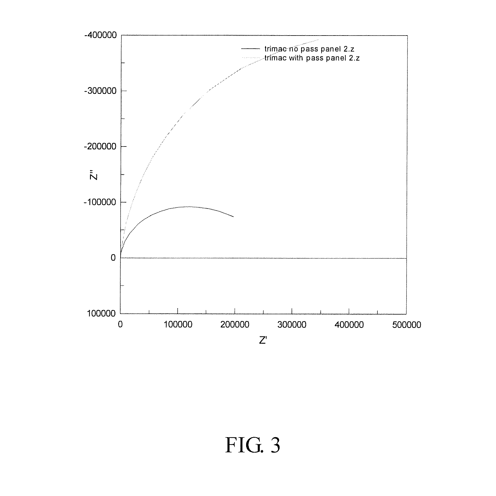
[0047]Test panels were prepared in the same manner as in Comparative Example 1 except that the chromium coating was applied from a trivalent electrolyte (Trimac III, available from MacDermid, Inc.). This produces a chromium coating containing up to 2% sulfur and also having up to 0.5% carbon codeposited with the chromium, effectively making it an alloy. Again, two panels were left unpassivated and two were passivated using the same process as described in Comparative Example 1. Again, EIS was used to examine the panels to determine the polarization resistance.

[0048]The results of these tests are shown in FIGS. 3 and 4 (Nyquist and Bode plots).

[0049]Here, it can be seen that the situation is reversed and that the passivated panel has the higher polarization resistance. This is supported by the bode plot which again shows the two time constants for the passivated panel and only one for the unpassivated panel. In this case, the calculated values of the polarization resistance are 1.8×1...

example 2

[0050]Test panels were prepared in the same manner as in Comparative Example 1 except that the chromium coating was applied from a trivalent electrolyte (Trimac III, available from MacDermid, Inc.). One of the panels was left unpassivated, one was cathodically passivated in a solution of potassium dichromate and one was passivated using the process solution as described in Comparative Example 1.

[0051]The panels were exposed to a neutral salt spray accelerated corrosion test (ASTM B117) for 72 hours and the results were compared as shown in FIG. 5. As seen in FIG. 5, the unpassivated panel (left panel) showed major red rust corrosion and some red rust was also evident on the panel passivated in hexavalent chromium (center panel). By comparison, there was no corrosion evident on the panel passivated in accordance with the compositions described herein.


PUM

PropertyMeasurementUnit
Timeaaaaaaaaaa
Timeaaaaaaaaaa
Angleaaaaaaaaaa

Abstract

A method of treating a substrate, wherein the substrate comprises a layer deposited from a trivalent chromium electrolyte, is described. The method includes the steps of providing an anode and the chromium(III) plated substrate as a cathode in an electrolyte comprising (i) a trivalent chromium salt; and (ii) a complexant; and passing an electrical current between the anode and the cathode to passivate the chromium(III) plated substrate. The substrate may be first plated with a plated nickel layer so that the chromium(III) plated layer is deposited over the nickel plated layer.

Description

FIELD OF THE INVENTION[0001]The present invention relates generally to a method of imparting improved corrosion protection to chromium plated substrates, which have been plated with chromium from a Cr+3 plating bath.BACKGROUND OF THE INVENTION[0002]A variety of compositions and processes have been used or suggested for use in order to impart improved corrosion resistance to chromium plated substrates to prevent the formation of rust spots when exposed to a corrosive environment. The use of nickel / chromium electrodeposits on a metal or plastic substrate to provide a decorative and corrosion resistant finish is also well known.[0003]Traditionally, the nickel underlayer is deposited electrolytically from an electrolyte based on nickel sulfate or nickel chloride, and boric acid. This electrolyte also typically contains organic additives to make the deposit brighter and harder and also to confer leveling (i.e., scratch hiding) properties. The organic additives also control the electroche...

Claims


Application Information

Patent Timeline
IPC IPC(8): C25D3/06
CPCC25D3/06C25D9/08C25D5/48Y10T428/12854C25D11/38
Inventor MERTENS, MARCTOOTH, RICHARDPEARSON, TREVORHERDMAN, RODERICK D.CLARKE, TERENCE
Owner MACDERMID ACUMEN INC
Why Eureka
Try Eureka