
Adaptive nonlinear current observer for boost pfc ac/dc converters

a nonlinear current observer and converter technology, applied in the field of power converters, can solve the problems of increasing the complexity of the implementation of the control system, affecting the performance affecting the accuracy of hall effect sensors,

Active Publication Date: 2015-09-17
SPARQ SYST INC
View PDF2 Cites 20 Cited by
  • Summary
  • Abstract
  • Description
  • Claims
  • Application Information

AI Technical Summary

Benefits of technology

The present invention provides systems, methods, and devices for estimating the inductor current and output voltage in a power factor correction boost converter. The control system uses an adaptive observer subcircuit that estimates the inductor current and output voltage using a combination of the input voltage and output voltage. The control system also includes an adaptive nonlinear observer circuit for estimating the inductor current and output voltage. The invention allows for more accurate control of the power factor correction boost converter, leading to improved performance and efficiency.

Problems solved by technology

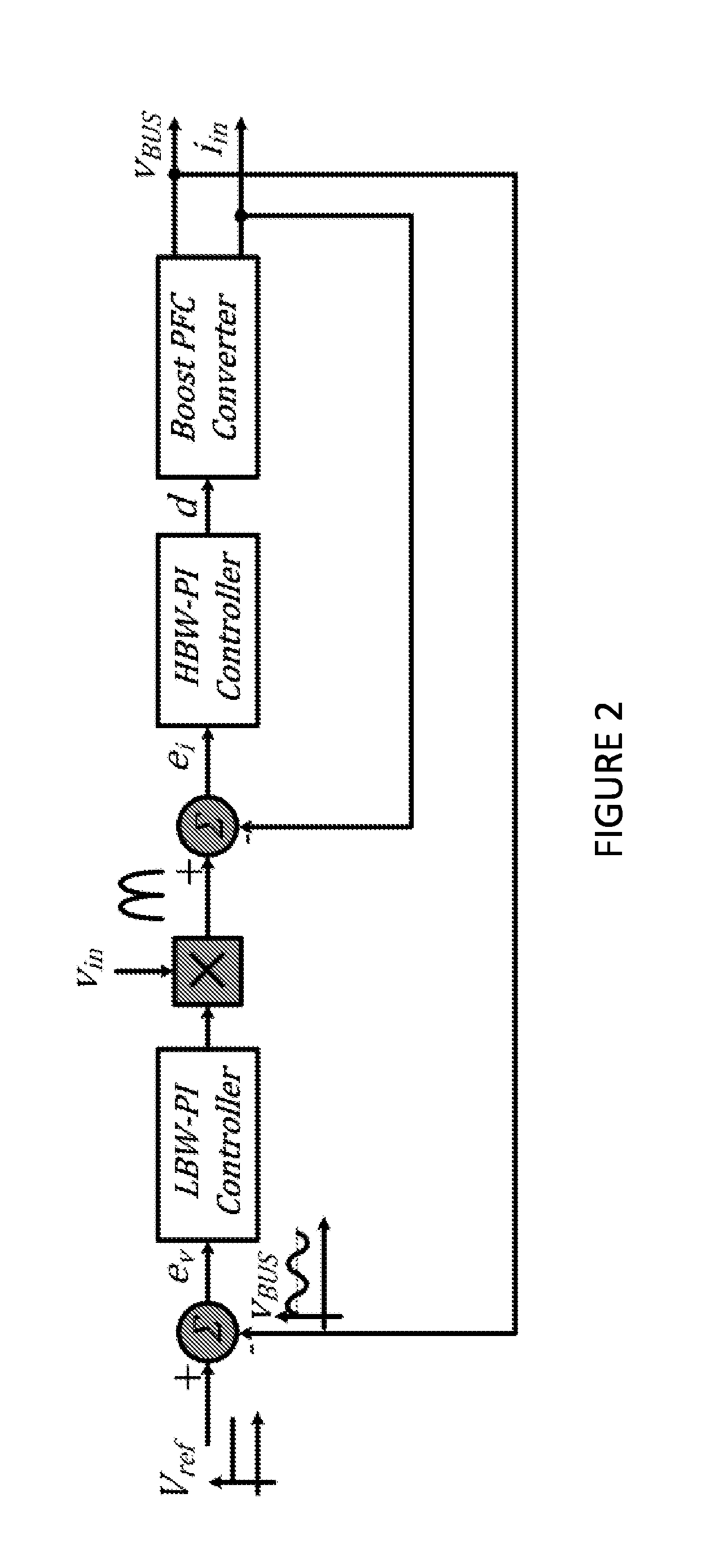
There are fundamental challenges in both external voltage loop and internal current loop of the conventional control system.
However, Hall effect sensors suffer from several practical difficulties.
This algorithm increases the complexity of the implementation of the control system.
As well, the bandwidth of the Hall effect sensors are limited and they introduce delay into the closed-loop control system.
This delay may jeopardise the stability of the control system.
Finally, Hall effect sensors are very costly and can significantly contribute to the overall cost of the converter.
Also, they increase the power losses of the converter.
These power losses are not preferable, especially in higher power applications.
These resistive current sensors are also very costly in applications where a very precise current value is required.
However, the current measurement using a CT creates some major difficulties for the converter.
Placing a CT in series with the boost power semiconductor increases the inductive path and causes high voltage spikes across the power semiconductors during the switching transitions.
Also, CTs restrict the maximum duty cycle of the converter.
This issue is very pronounced at the zero crossings of the input voltage where the converter should operate with a very high duty ratio.
Another issue related to the use of CTs for sensing current occurs when multiple boost converters are interleaved to share the current and to effectively reduce the input current ripple in higher power applications. FIG. 4 shows a two phase interleaved boost converter.
However, due to the phase-shift between the boost phases, the switching noise of one phase may affect the sampling of the next phase.
This highly degrades the reliability of the control system.
Nevertheless, the low-pass filter introduces delay to the control loop and deteriorates the stability margins.
While this attempt seems to provide a very simple solution for boost PFC converter, it is very sensitive to the converter parameters.
In particular, at light loads the performance of the converter significantly degrades especially close to the current zero crossings.
However, this approach is only useful for applications where the load variations are very limited and where a high quality input current is not required.
This further attempt demonstrated high quality input current for heavy loads but the current quality deteriorates at light loads.
However, the particular topology of the boost PFC converter makes the design of the observer very challenging.
Also, in many applications, the load information is not available for the observer to be used in the observer structure.
The other difficulty related to this particular topology is that the converter loses its observability at certain operating conditions.

Method used


Image

  • Adaptive nonlinear current observer for boost pfc ac/dc converters
  • Adaptive nonlinear current observer for boost pfc ac/dc converters
  • Adaptive nonlinear current observer for boost pfc ac/dc converters

Examples


Embodiment Construction

[0115]This description is organized as follows: A mathematical modelling of the AC / DC converter is presented in Section I. In Section II, an adaptive nonlinear current observer according to one aspect of the invention is explained. The stability of this nonlinear observer for boost PFC converters is then discussed in Section III. In Section IV, a qualitative analysis of the closed-loop control system from geometric point of view is presented. In Section V, the performance of the sensorless control system is verified through simulation. Experimental results from an industrial prototype of the control system are then given in section VI. It should be noted that the section headings are only provided for the reader's convenience and are not meant to form part of the disclosure.

[0116]As will be shown below, it can be mathematically proven that the boost PFC converter is not observable at zero crossings of the input voltage. Because of this, the observer can not provide proper informatio...


PUM


Abstract

Systems, methods, and devices which estimate the inductor current in a power factor correction (PFC) converter for use with AC / DC converters. A control system for use with the PFC takes as input the input voltage and the output voltage of the PFC. Control signals for power semiconductor subcircuits in the PFC are then output from the control system. The control system uses an adaptive observer sub-circuit that estimates the inductor current and the bus voltage. The adaptive observer uses an adaptive updater which uses both the estimates and the estimate error to update the adaptive observer's estimates.

Description

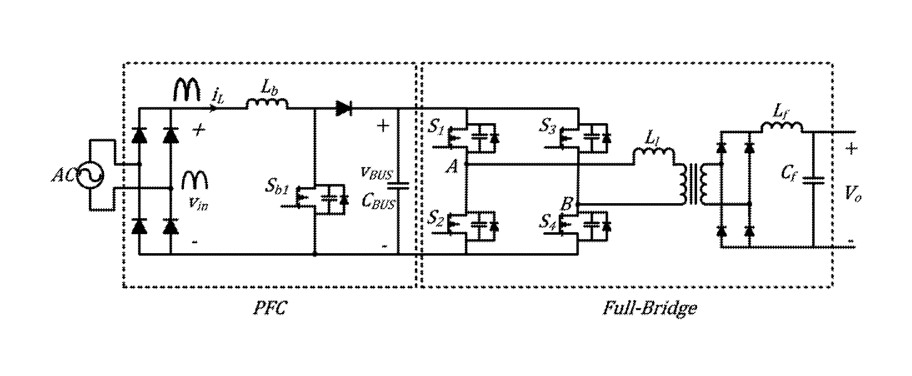
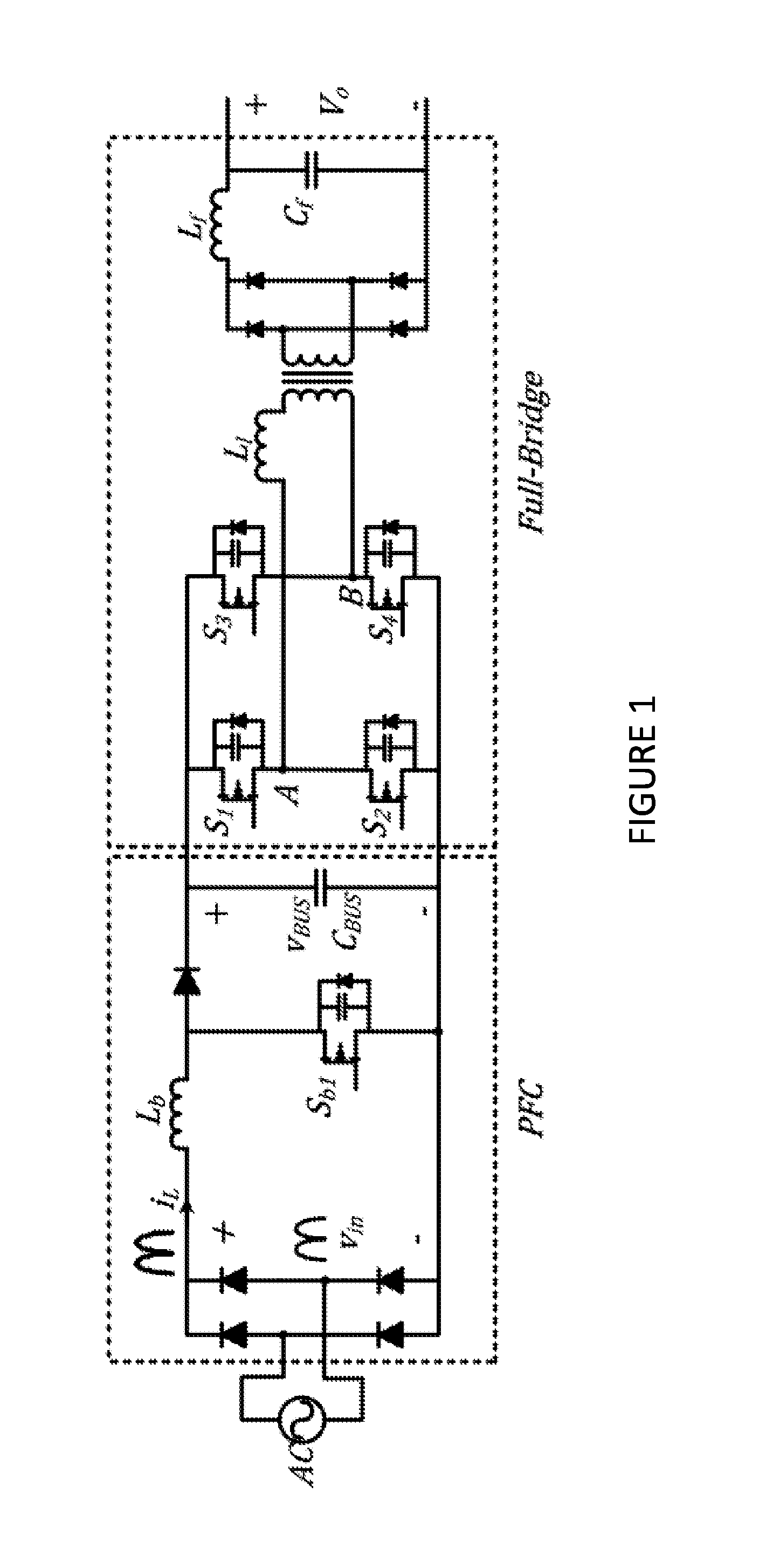
TECHNICAL FIELD[0001]The present invention relates to power converters. More specifically, the present invention relates to circuits, methods, and systems for estimating an inductor current in a power factor correction converter.BACKGROUND OF THE INVENTION[0002]AC / DC single-phase power conversion systems are widely used in industry to convert available electrical energy from the utility mains to a DC output voltage. In various industrial applications such as telecom, network server power supplies, plug-in and hybrid electric vehicles, etc., AC / DC converters are extensively employed to provide an isolated DC voltage from 12V to 600V. For applications in the range of few kilo-watts, AC / DC power conversion systems generally consist of a single phase front-end power factor correction (PFC) converter followed by an isolated full-bridge PWM converter as shown in FIG. 1. The front-end converter must comply with the stringent regulatory standards on the input current harmonics imposed by di...

Claims


Application Information

Patent Timeline
IPC IPC(8): H02M1/42H02M3/335H02M1/00
CPCH02M3/33507H02M1/4208H02M1/4225Y02B70/10H02M1/0009H02M3/1586H02M3/335
Inventor PAHLEVANINEZHAD, MAJIDJAIN, PRAVEEN
Owner SPARQ SYST INC
Learn More