Method for blow molding metal containers

a metal container and blow molding technology, applied in the field of metal container blow molding, can solve the problems of inefficient heating to anneal impact extruded preform by convection, impact extruded preform is subject to localized failure of preform material upon further deformation, and is known to be subject to significant work hardening and a very high dislocation density, so as to achieve significant work hardening and high dislocation density , the effect of increasing the wall thickness

Active Publication Date: 2015-10-01
MONTEBELLO TECH SERVICES LTD +1
View PDF8 Cites 9 Cited by
  • Summary
  • Abstract
  • Description
  • Claims
  • Application Information

AI Technical Summary

Benefits of technology

This patent describes a method for annealing metal workpieces to improve their strength and ductility. Annealing involves heating the material and then cooling it while maintaining a specific temperature for a specific time. This process helps to remove dislocations, realignment grains, and form a uniform grain structure. However, if the material is maintained at the annealing temperature for too long, grain growth occurs, which negatively impacts strength. To overcome this, the inventors found that using a die made of heat insulating material can prevent distortion of the preheating pattern and reduce energy consumption during preheating. This is because the heat non-conductive die material helps to stabilize the electromagnetic field and prevents interference with the induction heating of the preform.

Problems solved by technology

Impact extruded workpieces are known to be subject to significant work hardening and to a very high dislocation density.
Therefore, an impact extruded preform will be subject to localized failure of the preform material upon further deformation, especially expansion, without annealing of the preform material.
However, heating to anneal an impact extruded preform by convection is inefficient.
Heating by induction required multiple annealing steps in the past, thus making impact extruded preforms impractical for use in PRF.

Method used


Image

  • Method for blow molding metal containers
  • Method for blow molding metal containers
  • Method for blow molding metal containers

Examples


example

Preform

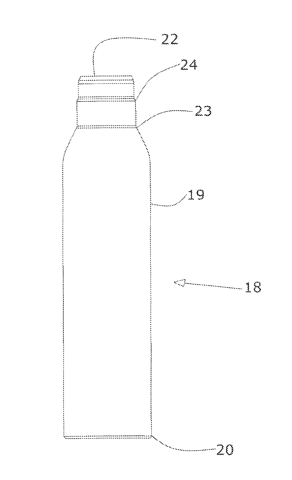
[0126]Commercially available aluminum slugs made of a Series 1100 or 3000 Alloy, having a 38 mm diameter and 12 mm thickness were impact extruded in a conventional impact extruder setup (Schuler Press) into an cylindrical aluminum preform of 38 mm diameter having a closed, flat bottom and a cylindrical sidewall of about 200 mm height and 0.333 mm thickness. The preform was subjected to conventional trimming, cleaning and brushing treatments, to generate an even top edge, remove extrusion lubricant and provide an overall even external appearance.

Annealing

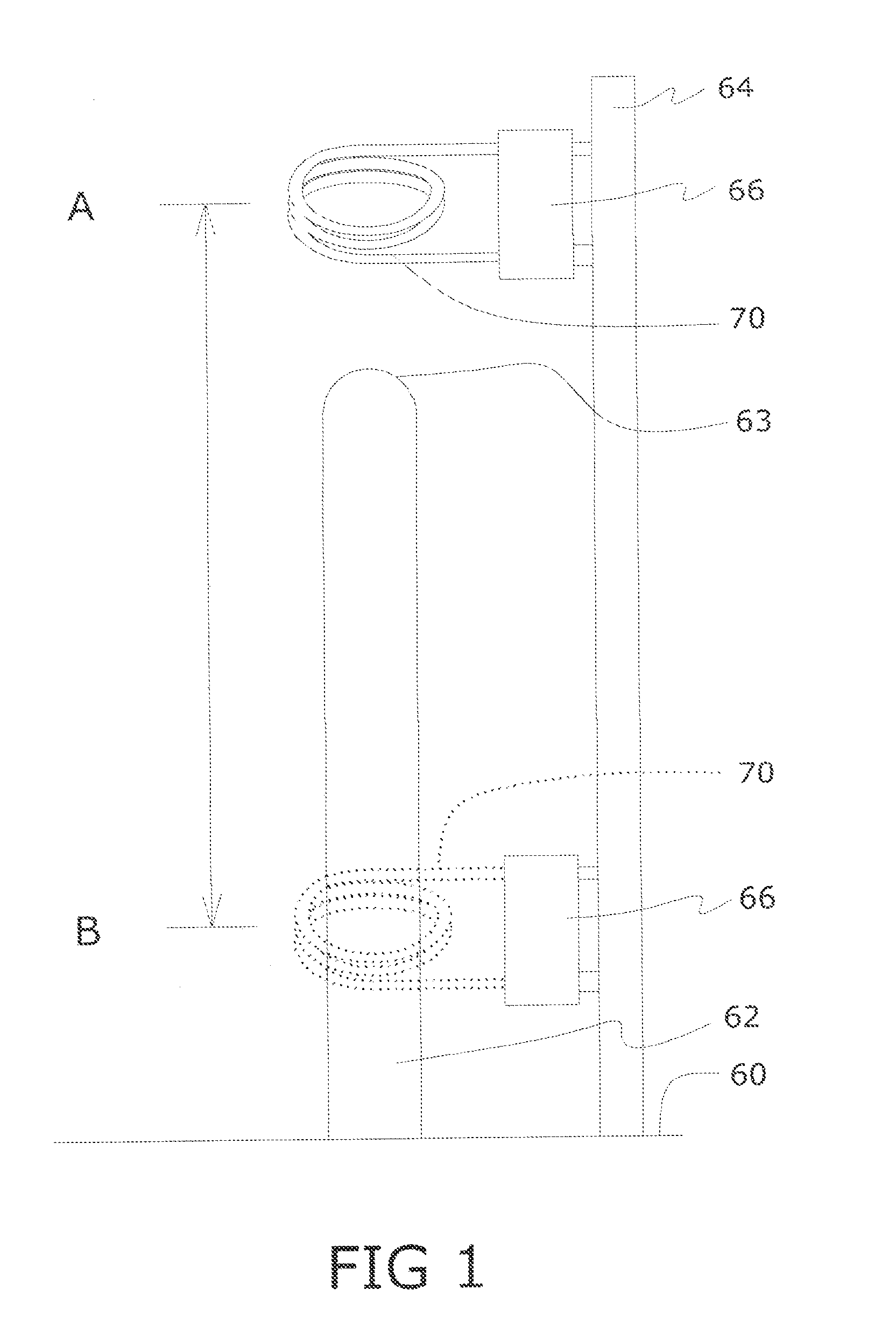
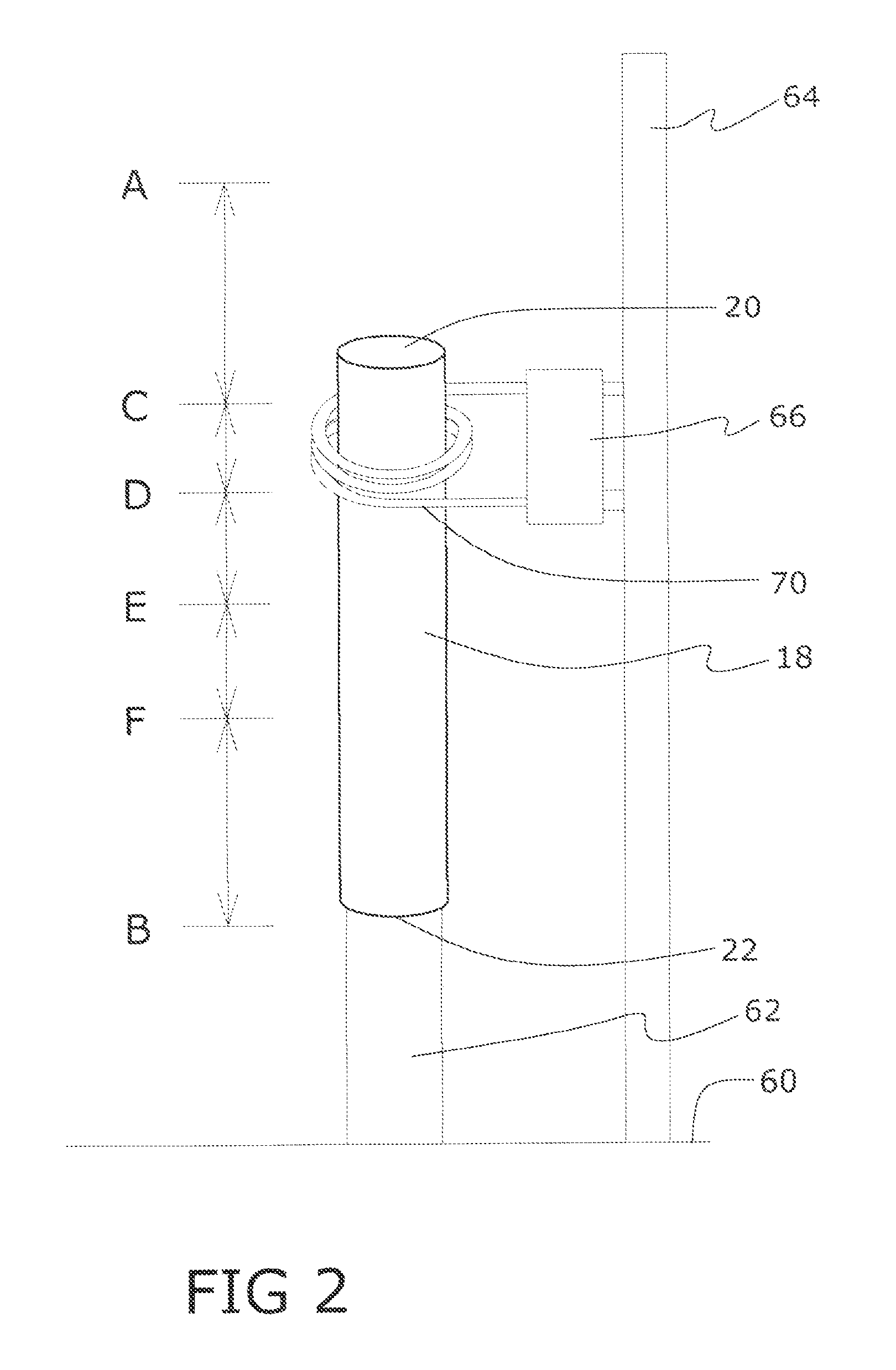
[0127]A commercially available cylindrical induction coil (FCF) of 42 mm diameter and about 50 mm height was used in the annealing treatment. The preform was placed on the mandrel 63 and the coil 70 was moved over the preform at constant speed. A voltage of 380V at a frequency of 300 Hz was applied to the coil at a total energy input of 15 kW. The efficiency of the induction heating process was calculated at about 38%, which t...


PUM

PropertyMeasurementUnit
Temperatureaaaaaaaaaa

Abstract

A method is disclosed for pressure forming a metal preform including shock annealing of the preform and subsequently preheating the preform prior to pressure forming. Shock annealing may be carried out as differential shock annealing in which different regions of the preform are annealed to different degrees. Preheating may be carried out by differentially preheating, optionally shock preheating, different regions of the preform for preheating at least those regions of the preform which will be subject to elevated expansion during pressure forming. Shock annealing by induction heating can lower energy consumption, reduce processing times and allow for larger expansion of the preform.

Description

[0001]This application claims priority under 35 U.S. C. §119(e) to U.S. Provisional Patent Application Ser. No. 61 / 970,103, filed Mar. 25, 2014, which is incorporated herein in its entirety by reference.[0002]The invention relates to methods and apparatus for forming metal containers or the like, utilizing internal fluid pressure to expand a hollow metal preform or workpiece against a die cavity, to produce a container having a contoured shape.[0003]Metal cans used for beverages and the like are either one-piece bodies, or bodies open at one or both ends and closed at those top and bottom ends by separate parts. Conventional cans generally have simple upright cylindrical sidewalls. For reasons of aesthetics, consumer appeal or product identification, it may be desired to impart the can with a more complex shape. For example, it may be desired to provide a metal container in the shape of a bottle rather than an ordinary cylindrical can shape, or to provide an ergonomically shaped bot...

Claims


Application Information

Patent Timeline
IPC IPC(8): B21D26/049C21D1/42H05B6/10C22F1/04C21D9/00B21D26/14C22C21/00
CPCB21D26/049B21D26/14C21D1/42H05B6/101C22F1/04C21D9/0068C22C21/00C21D2221/00C21D2221/10C21D7/12C21D9/08C21D1/26Y10T29/49805Y02P10/25B21D15/10B21D51/24
Inventor PILON, BETTY JEANSTATHOPOULOS, PETERGEORGIEV, GEORGIPILON, BENJAMIN JOSEPH
Owner MONTEBELLO TECH SERVICES LTD
Why Eureka
Try Eureka