Eureka AIR delivers breakthrough ideas for toughest innovation challenges, trusted by R&D personnel around the world.

Article for use in high stress environments having multiple grain structures

Inactive Publication Date: 2015-10-01
GENERAL ELECTRIC CO
View PDF0 Cites 7 Cited by
  • Summary
  • Abstract
  • Description
  • Claims
  • Application Information

AI Technical Summary

Benefits of technology

The patent describes a method of making an article by heating metal and then putting it into a mold. The metal is cooled from one side to the other, forming a solidification interface. The rest of the metal is then cooled from multiple directions. This results in a part for a turbine that has a base and an airfoil, with the first portion having directionally solidified grains and the second portion having equiaxed grains. This long grain size allows for better strength and better resistance to stress.

Problems solved by technology

Articles exposed to high temperature environments can experience stress cracking due to localized stress within the article.
If not mitigated a stress crack can propagate through the article and result in failure of the article, such as creep, thermal fatigue, and the like.
However, repairs of this kind can be disruptive and can be expensive.
However, even these materials can be subject to stress induced cracking and can require periodic repair.
These high strength alloys can have poor weldability which can make repair by welding difficult and can thereby make the component unrepairable.

Method used


Image

  • Article for use in high stress environments having multiple grain structures
  • Article for use in high stress environments having multiple grain structures
  • Article for use in high stress environments having multiple grain structures

Examples


embodiment 1

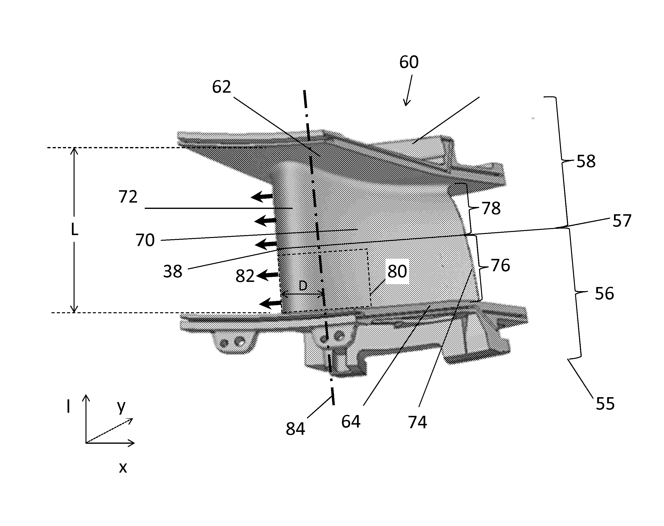
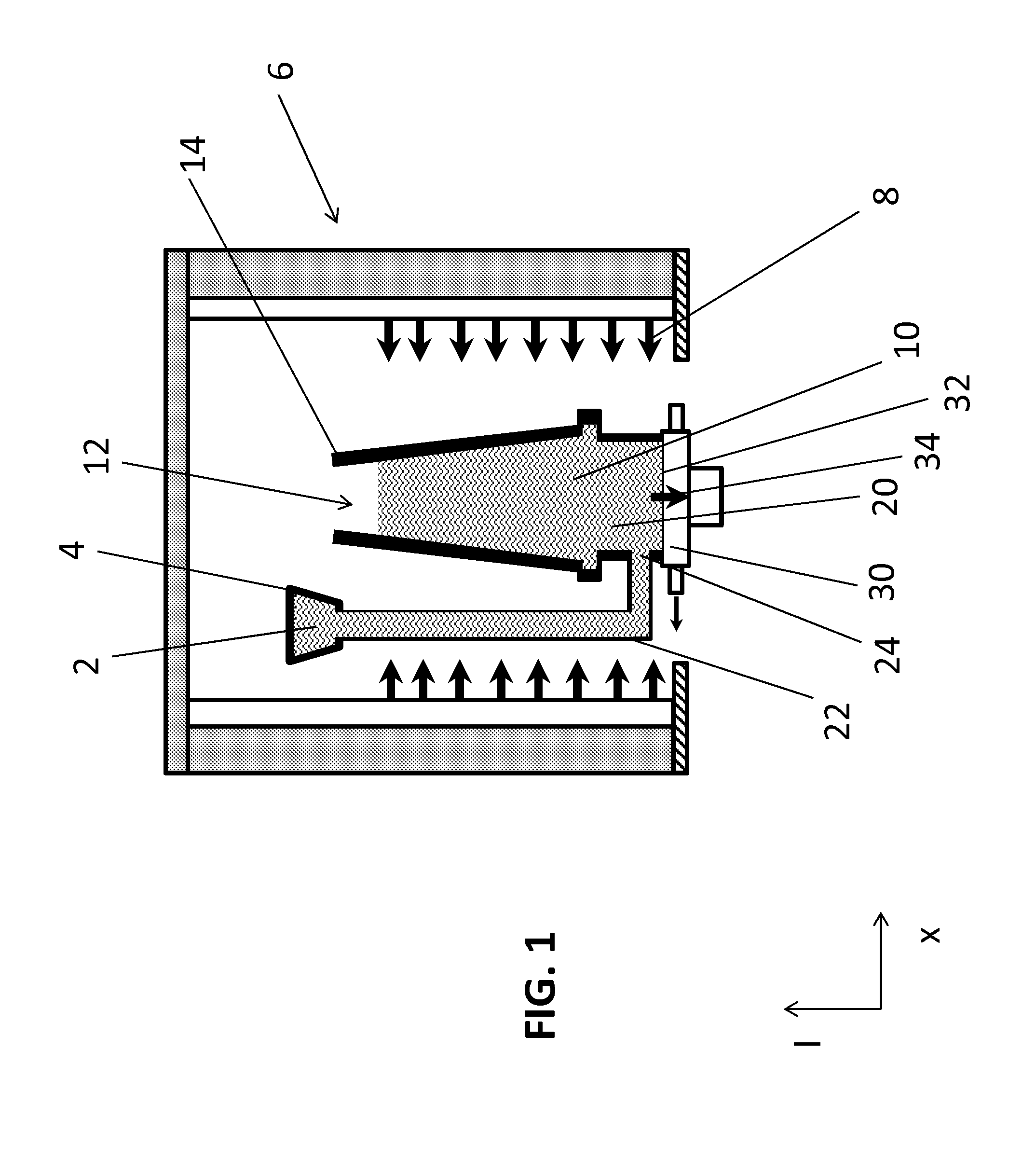
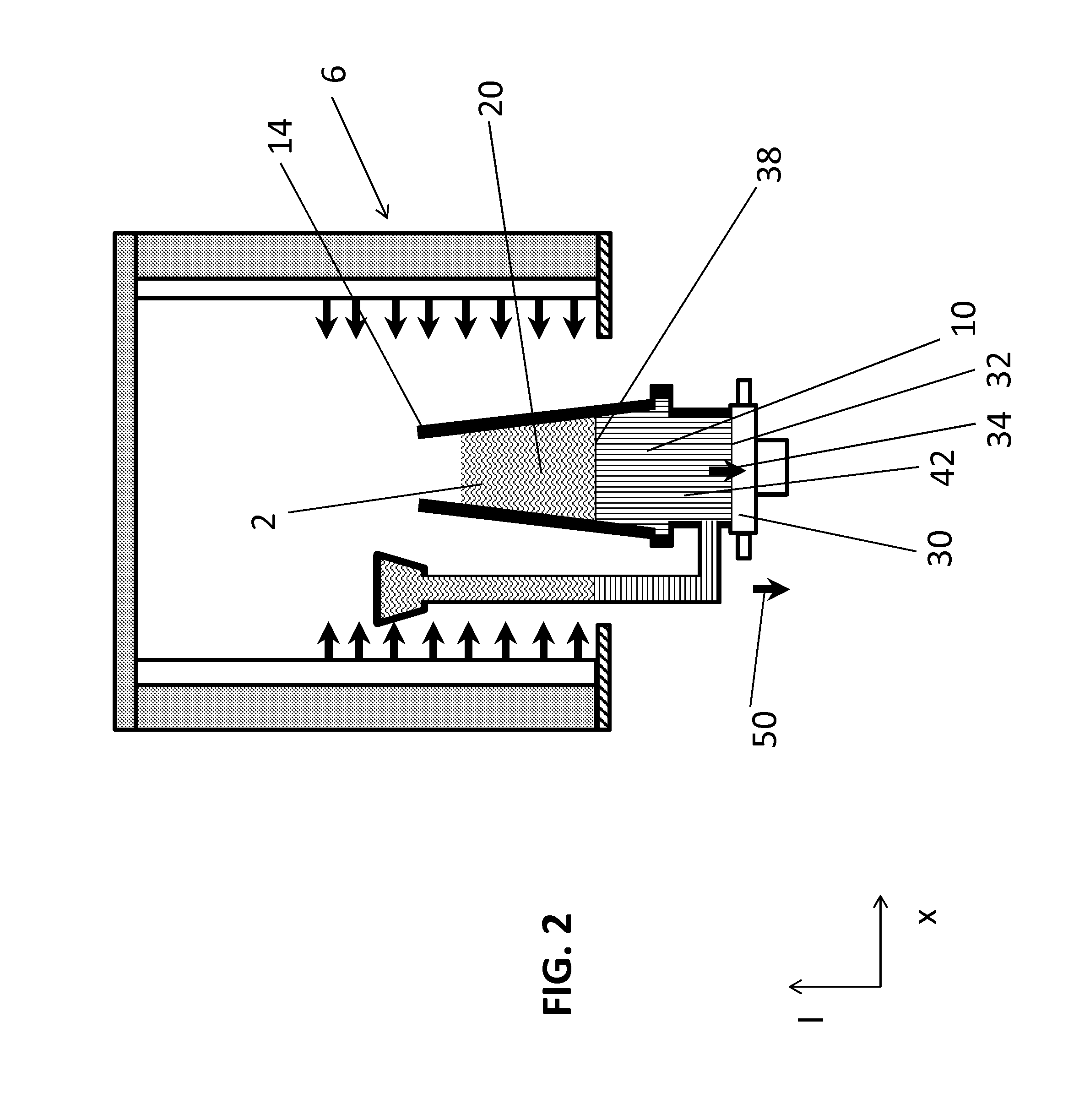
[0054] A method of forming an article comprising: heating a metal to form a molten metal having a metal temperature; heating a mold to a mold temperature greater than or equal to the metal temperature; introducing the molten metal to the mold; cooling a first portion of the molten metal while maintaining a second portion of the molten metal at the metal temperature, wherein the first portion has a first side and a second side, wherein the second side is opposite the first side and adjacent to the second portion, and wherein the cooling comprises progressively cooling the first portion from the first side to the second side such that a solidification interface progresses from the first side to the second side; and cooling the remainder of the molten metal from multiple directions after the first portion is cooled to less than or equal to a crystallization temperature.

[0055]Embodiment 2: The method of Embodiment 1, wherein cooling the remainder of the molten metal further comprises co...

embodiment 3

[0056] The method of any of Embodiments 1-2, wherein a volume of the first portion is greater than or equal 20% of a total volume of the article.

embodiment 4

[0057] The method of any of Embodiments 1-3, comprising determining a higher stress area of the article.


PUM

PropertyMeasurementUnit
Fractionaaaaaaaaaa
Percent by massaaaaaaaaaa

Abstract

A method of forming an article can comprise heating a metal to form a molten metal having a metal temperature; heating a mold to a mold temperature greater than or equal to the metal temperature; introducing the molten metal to the mold; cooling a first portion of the molten metal while maintaining a second portion of the molten metal at the metal temperature, wherein the first portion has a first side and a second side, wherein the second side is opposite the first side and adjacent to the second portion, and wherein the cooling comprises progressively cooling the first portion from the first side to the second side such that a solidification interface progresses from the first side to the second side; and cooling the remainder of the molten metal from multiple directions after the first portion is cooled to less than or equal to a crystallization temperature.

Description

CROSS REFERENCE TO RELATED APPLICATION[0001]This application claims priority to U.S. Provisional Application Ser. No. 61 / 971,109, filed Mar. 27, 2014, the content of which is hereby incorporated in its entirety.BACKGROUND OF THE INVENTION[0002]The subject matter disclosed herein relates to an article for use in high stress environments and the method of manufacturing the same. More particularly, the subject matter relates to enhancing durability of articles used in the hot section of a turbine.[0003]Articles exposed to high temperature environments can experience stress cracking due to localized stress within the article. This localized stress can be caused by a temperature gradient within a material which can lead to different rates of expansion. Portions of the material can expand more rapidly and can induce a tension force on adjacent areas. If not mitigated a stress crack can propagate through the article and result in failure of the article, such as creep, thermal fatigue, and ...

Claims


Application Information

Patent Timeline
IPC IPC(8): F01D5/28B22D21/02C22C19/05B22D27/04
CPCF01D5/28C22C19/057B22D21/025B22D27/045B22D30/00F01D5/14F01D9/02F05D2230/21F01D5/12Y02T50/60
Inventor CUI, YANFENG, GANJIANGKOTTILINGAM, SRIKANTH CHANDRUDULAYLOCK, MATTHEW JOSEPHLIN, DECHAO
Owner GENERAL ELECTRIC CO
Why Eureka
Eureka Blog
Learn More