Fiber optic temperature sensor utilizing a phosphor microsphere

a temperature sensor and fiber optic technology, applied in the field of fiber optic temperature sensors utilizing phosphor microspheres, can solve the problem of limited flexibility of probes, and achieve the effect of improving coupling efficiency and increasing the absorption of excitation ligh

Active Publication Date: 2015-10-01
DJEU NICHOLAS I
View PDF5 Cites 14 Cited by
  • Summary
  • Abstract
  • Description
  • Claims
  • Application Information

AI Technical Summary

Benefits of technology

[0008]The difference between the present invention and prior art is that here one has an air gap between the optical fiber and the phosphor microsphere, except for a single point of contact between the end of the fiber and the microsphere. In this way, the part of the microsphere facing the fiber end acts as a lens. As such, it causes some rays entering the microsphere to have a significantly longer path within the microsphere, thus increasing

Problems solved by technology

With currently available materials, the flexible probe will be li

Method used


Image

  • Fiber optic temperature sensor utilizing a phosphor microsphere
  • Fiber optic temperature sensor utilizing a phosphor microsphere
  • Fiber optic temperature sensor utilizing a phosphor microsphere

Examples


first embodiment

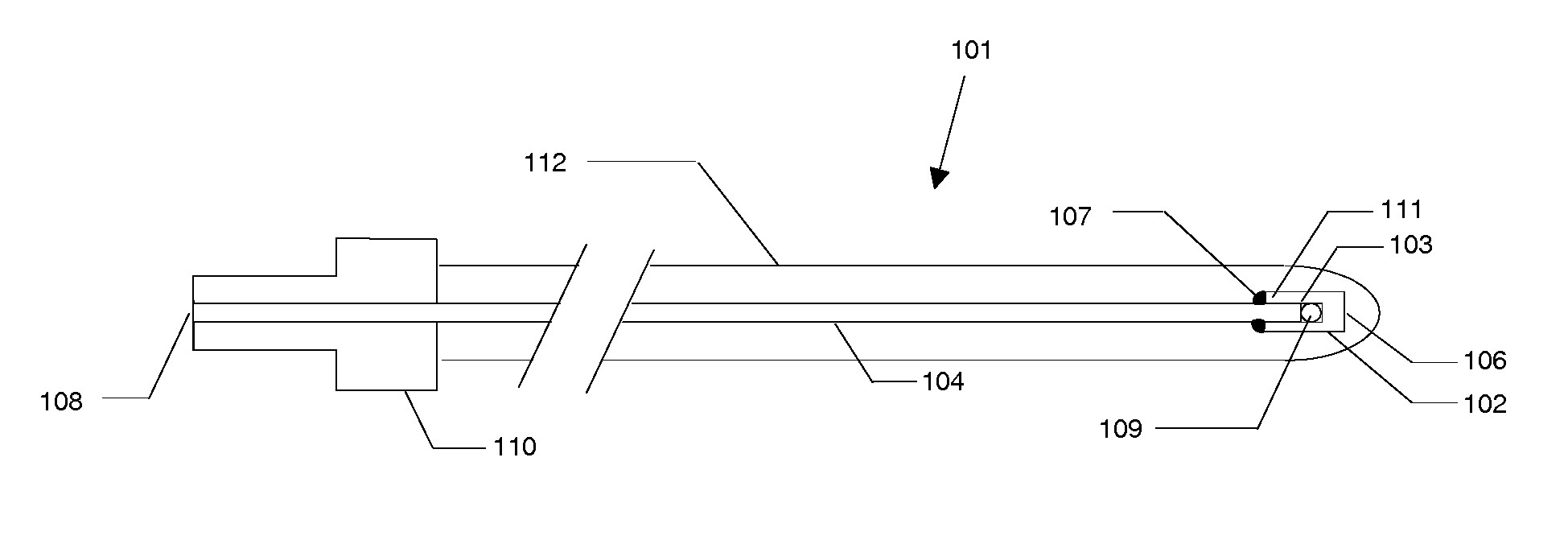
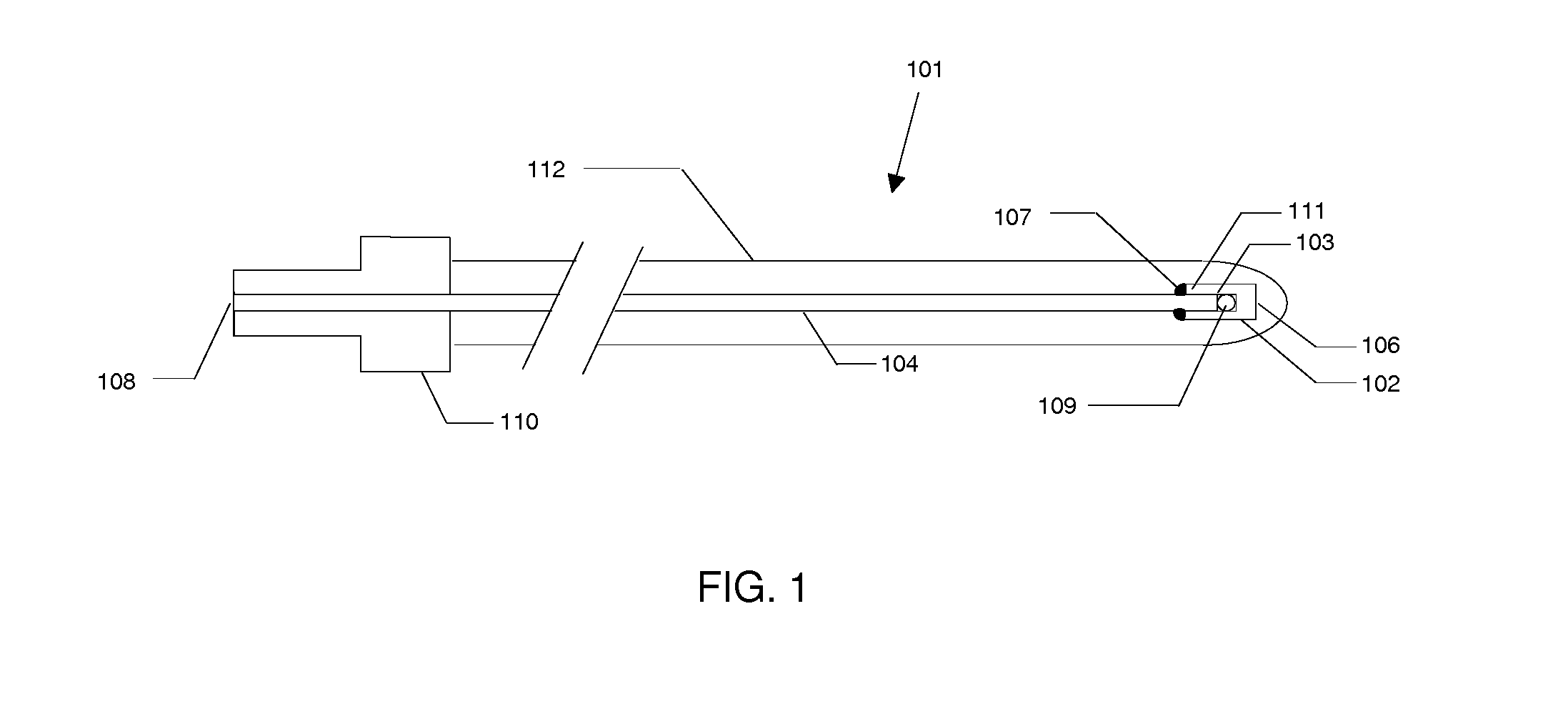
[0037]FIG. 1 illustrates the present invention, a flexible fiber optic thermal probe 101 utilizing a phosphor microsphere 109. The sensor end 103 of an optical fiber 104 is polished and held in contact with the phosphor microsphere 109 inside a ceramic tube 102 having a closed end 106 and an open end 111. Note, however, that the contact occurs at only a single point. Thus, for all intent and purposes, the phosphor microsphere 109 is surrounded by air, which has a much lower index of refraction. Such a construction endows the phosphor microsphere 109 with a built-in lens. The result is that the coupling of the excitation light into the phosphor microsphere 109, as well as of the fluorescence produced therein back into the fiber, are improved. The phosphor microsphere 109 should have a diameter substantially the same as that of the optical fiber 104. The inside diameter of the ceramic tube 102 is sized to be just large enough so as to allow the phosphor microsphere 109 and the optical...

second embodiment

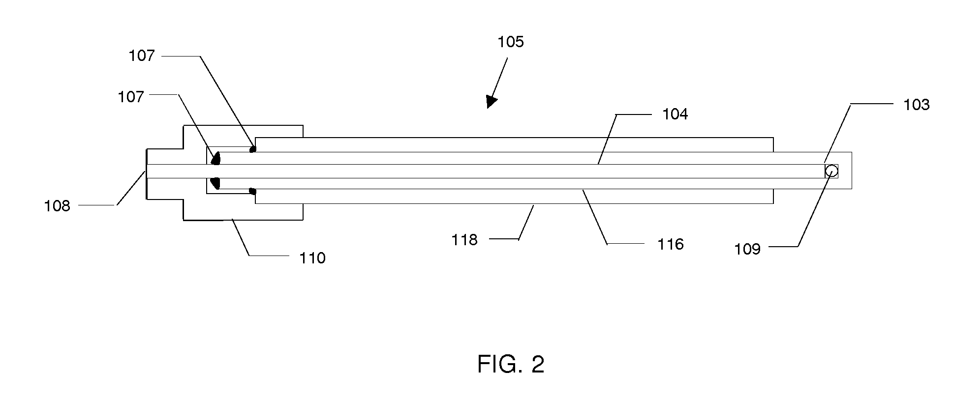
[0038]FIG. 2 illustrates the current invention, a rigid fiber optic thermal probe 105 utilizing a phosphor microsphere 109. The phosphor microsphere 109 is placed in a close fitting closed-ended thin ceramic tube 116. Then an optical fiber 104 with sensor end 103 that is polished is inserted until it makes contact with the phosphor microsphere 109. The diameter of the optical fiber 104 is substantially the same as that of the phosphor microsphere 109. The optical fiber 104 is bonded to the thin ceramic tube 116 at its open end with adhesive 107. Next, the thin ceramic tube 116 is inserted into a close fitting thick ceramic tube 118 for protection, and bonded to the thick ceramic tube 118 with adhesive 107. Finally, the entire assembly is put into a fiber connector 110, and the connector end 108 of the optical fiber 104 is terminated therein.

[0039]The performance and cost of the thermal probe is determined by its desired range of operation. For example, the optical fiber 104 in the r...


PUM


Abstract

In accordance with the present invention, a fiber optic temperature sensing system incorporating a thermal probe which utilizes a phosphor in the form of a microsphere is provided. The microsphere is situated in air so as to produce a lensing effect in both coupling the excitation light delivered to it by the fiber and coupling the fluorescence produced by the phosphor material back into the fiber. The thermal probe can be implemented in either a flexible or a rigid form. Materials for the phosphor microspheres include—but are not limited to—rare earth(s) doped single crystals, rare earth(s) doped ceramics, and ruby. When coupled to a suitable controller, these thermal probes can provide reliable temperature measurements even in environments characterized by strong electrical noise or electromagnetic interference.

Description

CROSS-REFERENCE TO RELATED APPLICATIONS[0001]This application claims the benefit of the U.S. Provisional Patent Application No. 61 / 757,743 filed Jan. 29, 2013 by the present inventor. This provisional patent application is incorporated herein by reference.BACKGROUND OF THE DISCLOSURE[0002]One type of fiber optic temperature sensor is based on the decay time of the fluorescence emitted by a phosphor, which serves as the active element of its thermal probe. An optical fiber connects the phosphor element, either directly or via a patch cable, to a controller. The controller provides the optical excitation of the phosphor, and receives and analyzes some of its fluorescent emission. When the decay time of the fluorescence exhibits a monotonic dependence on the temperature of the phosphor, a thermometer can be implemented once that dependence is established.[0003]The phosphor is usually in the form of a mini-rod made from a single-crystal material. When the appropriate material is used, e...

Claims


Application Information

Patent Timeline
IPC IPC(8): G01K11/32
CPCG01K11/32G01K11/20
Inventor DJEU, NICHOLAS I
Owner DJEU NICHOLAS I
Why Eureka
Try Eureka