Light source apparatus and information-obtaining apparatus using the same

a technology of information-obtaining apparatus and light source apparatus, which is applied in the field of light source apparatus and information-obtaining apparatus using the same, and can solve problems such as spectral resolution degradation

Inactive Publication Date: 2015-10-01
CANON KK
View PDF9 Cites 7 Cited by
  • Summary
  • Abstract
  • Description
  • Claims
  • Application Information

AI Technical Summary

Benefits of technology

[0012]A light source apparatus according to one or more of the present inventions is a light source apparatus emitting two pulse lights of which a center wavelength difference is variable, and the light source apparatus includes a light source configured to emit a first pulse light of which a center wavelength is variable, a nonlinear optical medium configured to generate a second pulse light having a center wavelength different from the first pulse light in response to incidence of the first pulse light, and a wavelength dispersion adjustment device configured to give a wavelength dispersion to the second pulse light, wherein a wavelength dispersion amount given by the wavelength dispersion adjustment device is variable. In one or more other embodiments, a light source apparatus may include: a light source configured to emit a first pulse light of which a center wavelength is variable; a nonlinear optical medium configured to generate a second pulse light having a center wavelength different from the first pulse light in response to incidence of at least a portion of the first pulse light and having a wavelength dispersion; and a first adjustment unit configured to adjust a chirp rate of the second pulse light corresponding to a changing center wavelength of the first pulse light.
[0013]An information-obtaining apparatus according to one or more of the present in

Problems solved by technology

For this reason, a Raman spectrum obtained from a subject includes a noise due to the frequency difference component t

Method used


Image

  • Light source apparatus and information-obtaining apparatus using the same
  • Light source apparatus and information-obtaining apparatus using the same
  • Light source apparatus and information-obtaining apparatus using the same

Examples


first embodiment

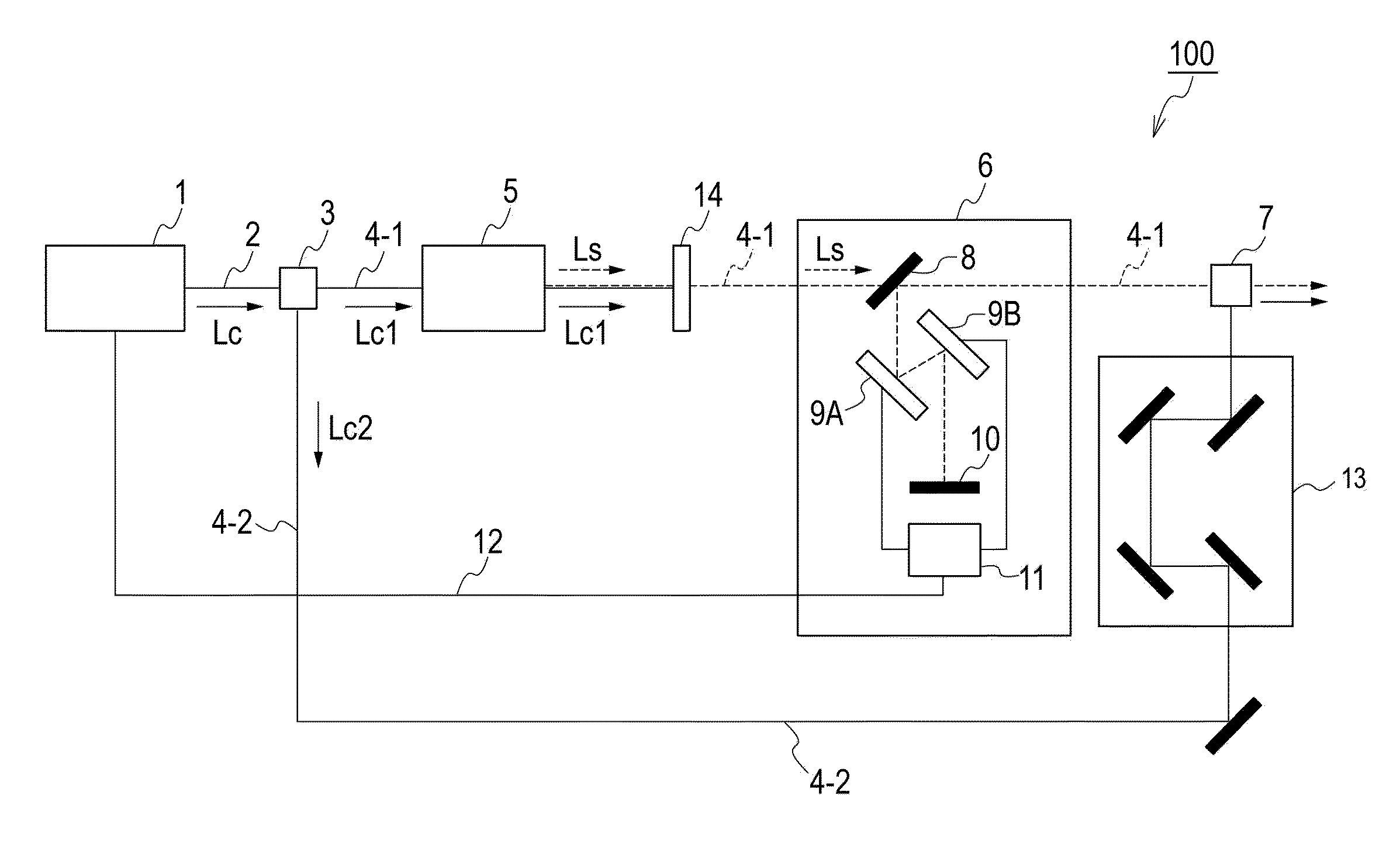
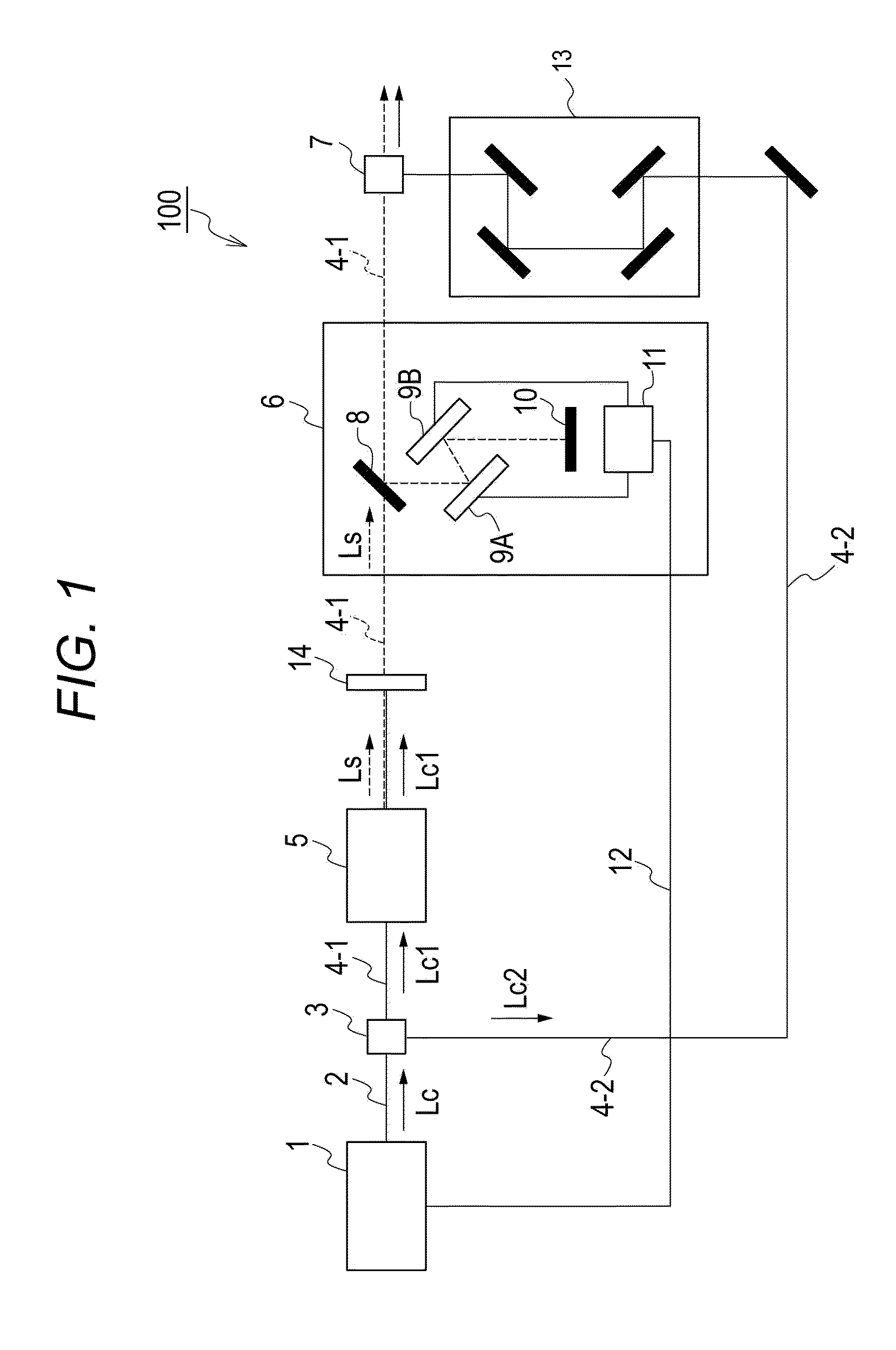
[0060]FIG. 1 illustrates a schematic view of a light source apparatus 100. A light source 1 can emit a first pulse light (excitation pulse light) of which center wavelength λC is variable. The light source 1 is preferably, for example, pulse laser having a wavelength filter in a laser resonator and capable of changing the wavelength within the gain band of the laser medium.

[0061]A first pulse light LC emitted from the light source 1 passes through an optical path 2, and branches, at a dividing device 3, into a light LC1 advancing to an optical path 4-1 and a light LC2 advancing to an optical path 4-2. The first pulse light LC1 branched to the optical path 4-1 is guided to a nonlinear optical medium 5. When the first pulse light is incident thereupon, the nonlinear optical medium 5 generates a second pulse light (generated pulse light) LS having a center wavelength λS different from the first pulse light according to the optical parametric gain of the nonlinear optical medium 5. The ...

second embodiment

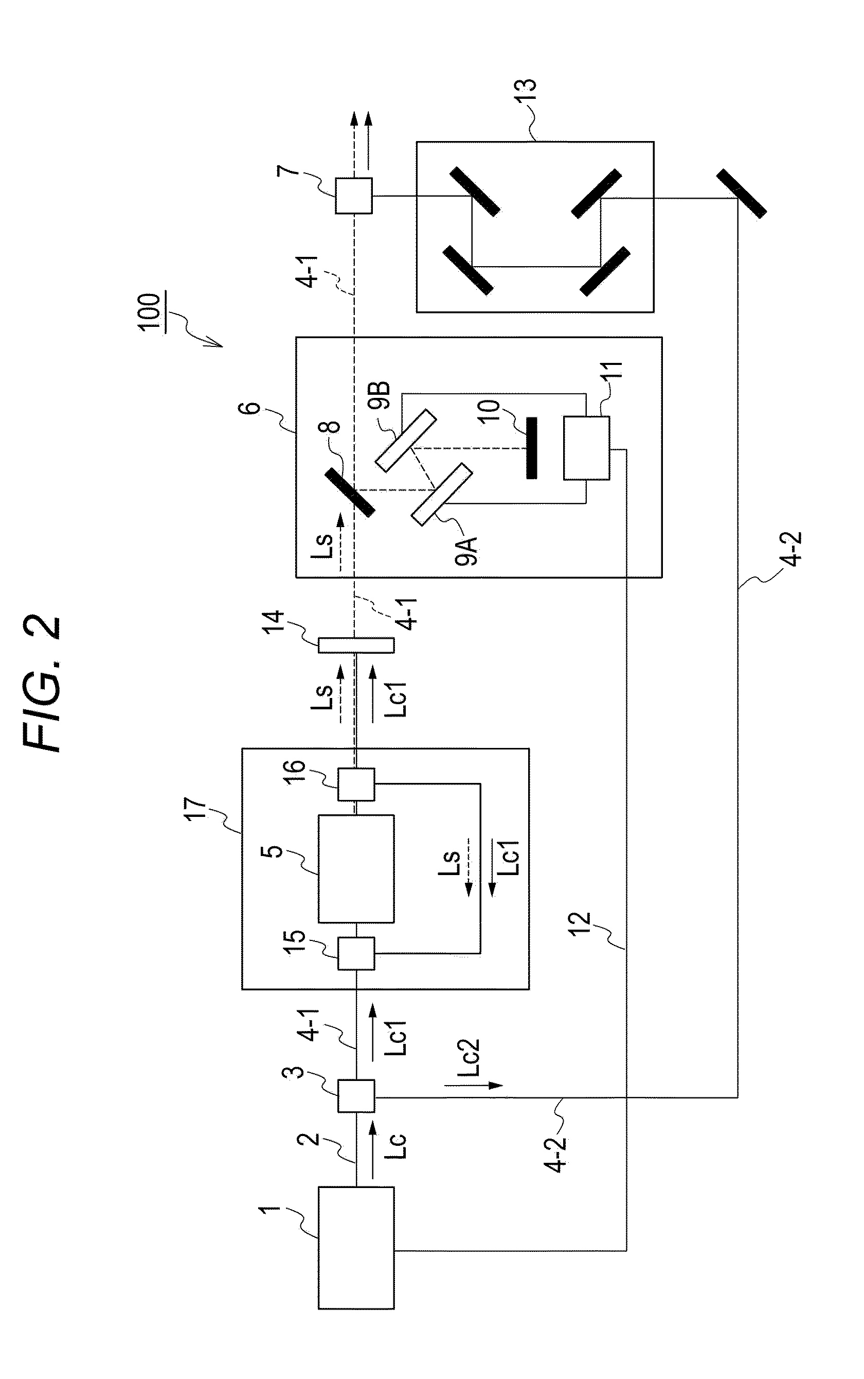
[0070]FIG. 2 illustrates another embodiment of a light source apparatus. The present embodiment is different from the light source apparatus according to the first embodiment in that the present embodiment has a fiber optical parametric oscillator (which may be hereinafter abbreviated as FOPO). For example, those shown in the first embodiment can be employed as the elements such as the dividing device 3, the nonlinear optical medium 5, wavelength dispersion adjustment devices 6-1, 6-2, and the like.

[0071]The first pulse light of the center wavelength 2 emitted from the light source 1 passes the optical path 2, and branches at the dividing device 3, to the light LC1 advancing to the optical path 4-1 and the light LC2 advancing to the optical path 4-2. The first pulse light LC1 branching to the optical path 4-1 is guided to a resonator (fiber optical parametric oscillator) 17 including the nonlinear optical medium 5 via the multiplexing device 15, and the second pulse light LS is gene...

third embodiment

[0076]FIG. 3 illustrates another embodiment of a light source apparatus. The present embodiment is different from other embodiments in that a signal light and an idler light generated by a nonlinear optical medium are emitted in response to incidence of excitation pulse light.

[0077]A first pulse light (excitation pulse light) LC of a center wavelength λC emitted from a light source 1 is caused to incident upon a nonlinear optical medium 5, so that two generated pulse lights, i.e., a second pulse light (signal light) LS1 of a center wavelength λS1 and a third pulse light (idler light) LS2 of a center wavelength λS2, are generated. Of the three pulse lights retrieved from the nonlinear optical medium 5, the first pulse light is cut off by the band pass filter 14, and thereafter, the dividing device 3 causes the light to be branched into a second pulse light LS1 and a third pulse light LS2. The second pulse light LS1 advances to an optical path 4-1, and a wavelength dispersion adjustme...


PUM


Abstract

A light source apparatus emitting two pulse lights of which center wavelengths are different from each other, and an information-obtaining apparatus for use with a light source apparatus, are provided. In at least one embodiment, the light source apparatus may include a light source configured to emit a first pulse light of which a center wavelength is variable, a nonlinear optical medium configured to generate a second pulse light having a center wavelength different from the first pulse light in response to incidence of the first pulse light, and a wavelength dispersion adjustment device configured to give a wavelength dispersion to the second pulse light, wherein a wavelength dispersion amount given by the wavelength dispersion adjustment device to the second pulse light is variable. In one or more embodiments, a light source apparatus may include an adjustment unit to adjust a chirp rate of the second pulse light.

Description

BACKGROUND OF THE INVENTION[0001]1. Field of the Invention[0002]The present inventions relate to light source apparatuses, such as, but not limited to, a light source apparatus emitting two pulse lights of which a center wavelength difference is variable, and to an information-obtaining apparatus using the same.[0003]2. Description of the Related Art[0004]Various kinds of information about constituent materials of a subject can be obtained by emitting a pulse light to the subject and detecting light reflected or scattered by the subject, detecting light passing through the subject, or detecting fluorescence emitted from the subject.[0005]In recent years, researches have been actively conducted, in which two pulse lights having a frequency difference corresponding to a molecular vibration number are emitted onto a subject, and light based on Stimulated Raman Scattering (SRS) and coherent anti-Stokes Raman scattering (CARS) that occurs with the subject, so that the material of the sub...

Claims


Application Information

Patent Timeline
IPC IPC(8): G01N21/65
CPCG01N21/65G01N2201/06113G01N2021/655
Inventor INOUE, YUKIHIROYONETANI, YUKI
Owner CANON KK
Why Eureka
Try Eureka