RF structure of user terminal for supporting multi-carrier aggregation and various communication radio access technologies

a multi-carrier aggregation and user terminal technology, applied in the direction of duplex signal operation, transmission path division, wireless communication, etc., can solve the problems of difficult inter-band ca, difficult inter-band ca, and difficult to meet the needs of multi-carrier aggregation and various communication radio access technologies. achieve the effect of reducing transmission power and reception sensitivity

Active Publication Date: 2015-11-05
LG ELECTRONICS INC
View PDF5 Cites 18 Cited by
  • Summary
  • Abstract
  • Description
  • Claims
  • Application Information

AI Technical Summary

Benefits of technology

[0010]Furthermore, an object of another disclosure of this specification is to solve a problem in that transmission power and reception sensitivity are reduced due to additional several devices.
[0011]In order to achieve the above object, one disclosure of this specification provides a terminal, comprising: a band-adjustable tunable antenna; a diplexer which is connected to the tunable antenna and aggregates and separates subcarriers; one or more antenna switches which are connected to the diplexer and aggregate and separate low band subcarriers and middle band and high band subcarriers; a subcarrier processing unit which is connected to the one or more antenna switch and aggregates and separates several subcarriers of a low band, several subcarriers of a middle band, and several subcarriers of a high band. A low noise amplifier is connected to the subcarrier processing unit in order to prevent a loss of reception sensitivity and an increase of a noise figure generated on a reception path of the diplexer, the one or more antenna switches, and the subcarrier processing unit.
[0012]In order to achieve the above object, another disclosure of this specification is a terminal, comprising: a band-adjustable tunable antenna; a diplexer which is connected to the tunable antenna and aggregates and separates subcarriers; a first antenna switch which is connected to the diplexer and aggregates and separates low band subcarriers and middle band and high band subcarriers; a second antenna switch which is connected to the diplexer and selects middle band and the high band subcarriers; a low band subcarrier processing unit which is connected to the first antenna switch and aggregates and separates several subcarriers of a low band; a middle band subcarrier processing unit which is connected to the second antenna switch and aggregates and separates several subcarriers of a middle band; and a high band subcarrier processing unit which is connected to the second antenna switch and aggregates and separates several subcarriers of a high band. A low noise amplifier is connected to the low band subcarrier processing unit in order to prevent a loss of reception sensitivity and an increase of a noise figure generated on a reception path of the diplexer, the first antenna switch, and the subcarrier processing unit. Also, a low noise amplifier is connected to the middle band subcarrier processing unit or the high band subcarrier processing unit in order to prevent a loss of reception sensitivity and an increase of a noise figure generated on a reception path of the diplexer, the second antenna switch, and the middle band subcarrier processing unit or the high band subcarrier processing unit.
[0019]In accordance with one disclosure of this specification, the proposed RF structure may support all of an intra-band CA, an inter-band CA, and various existing radio access technologies. Furthermore, in accordance with another disclosure of this specification, a problem in that a reduction of transmission power and reception sensitivity for added RF devices (a diplexer, a quadplexer, and a harmonic filter) can be solved.

Problems solved by technology

However, in the design of the RF structure of a user terminal, to support all of the intra-band CA, the inter-band CA, and existing several radio access technologies was impossible because the implementation of the intra-band CA, the inter-band CA, and existing several radio access technologies is very complicated.
Furthermore, if both the intra-band CA and the inter-band CA are implemented, there is a problem in that transmission power and reception sensitivity are reduced due to additional several devices.

Method used


Image

  • RF structure of user terminal for supporting multi-carrier aggregation and various communication radio access technologies
  • RF structure of user terminal for supporting multi-carrier aggregation and various communication radio access technologies
  • RF structure of user terminal for supporting multi-carrier aggregation and various communication radio access technologies

Examples


first embodiment

[0138]FIG. 12 is an exemplary diagram illustrating an RF structure capable of supporting both an inter-band CA and an intra-band CA in accordance with a

[0139]As described above, in accordance with the RF structure of a transmitter capable of supporting an intra-band CA and an inter-band CA, the RF structure of the transmitter was very complicated because the number of RF chains corresponding to the number of CCs is required. Furthermore, a band that an antenna can support was limited.

[0140]In accordance with the first embodiment illustrated in FIG. 12, several bands can be supported using a tunable antenna. That is, the tunable antenna may be varied according to several center frequencies. Furthermore, a multiple antenna technology can be easily implemented using several tunable antennas.

[0141]Specifically, in accordance with the first embodiment illustrated in FIG. 12, the tunable antenna is connected to a diplexer that aggregates / separates CCs. The diplexer is connected to an ante...

third embodiment

[0158]Furthermore, as described above, in order to overcome a loss of reception reference sensitivity caused because devices, such as a diplexer, a quadplexer, a harmonic filter for removing harmonics, and an antenna switch, are additionally used, in the third embodiment, a low noise amplifier (LNA) is added, but is placed after a duplexer. Accordingly, reception reference sensitivity can be efficiently improved. Specifically, this is described with reference to FIGS. 13a to 13c.

second embodiment

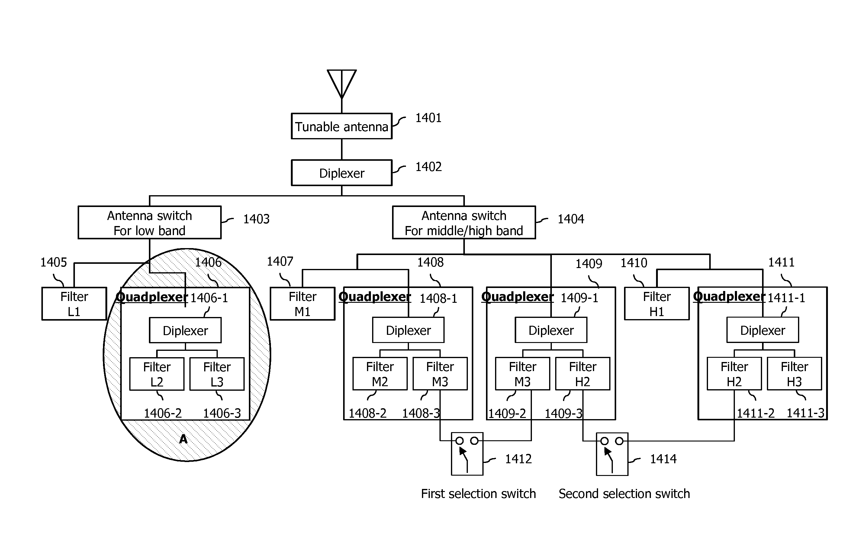
[0159]FIG. 13a is an exemplary diagram illustrating an RF structure capable of supporting both an inter-band CA and an intra-band CA in accordance with a

[0160]The RF structure illustrated in FIG. 13a is designed for an inter-band carrier aggregation in order to support a multi-band and a multi-mode and also improved in order to also support an intra-band carrier aggregation.

[0161]Devices included in the RF structure illustrated in FIG. 13a are configured to process a maximum of 40 MHz in one operating band in order to support an intra-band contiguous CA.

[0162]Furthermore, in accordance with the second embodiment illustrated in FIG. 13a, the CCs of several bands, such as the CC of a low band, the CC of a middle band, and the CC of a high band, can be supported using a tunable antenna 1301. The tunable antenna 1301 is configured according to a combination of supported bands, and thus can support all of inter-band carrier aggregations of a combination of a low band and a high band, a c...


PUM


Abstract

According to one embodiment of the present specification, a user terminal is provided. The user terminal can comprise: a tunable antenna capable of adjusting a band; a diplexer connected to the tunable antenna to synthesize and separate sub-carriers; one or more antenna switches connected to the diplexer to synthesize and separate low-band sub-carriers and middle-band and high-band sub-carriers; and a sub-carrier processing unit connected to the one or more antenna switches to synthesize and separate a plurality of low-band sub-carriers, a plurality of middle-band sub-carriers and a plurality of high-band sub-carriers. A low-noise amplifier can be connected to the sub-carrier processing unit in order to prevent an increase in a reception sensitivity loss and a noise index occurring on a reception path of the diplexer, the one or more antenna switches and the sub-carrier processing unit.

Description

BACKGROUND OF THE INVENTION[0001]1. Field of the Invention[0002]A disclosure of this specification relates to the RF structure of a terminal supporting all of an inter-band carrier aggregation, an intra-band carrier aggregation, and various radio access technologies.[0003]2. Related Art[0004]3GPP (3rd Generation Partnership Project) LTE (Long Term Evolution) that is an advancement of UMTS (Universal Mobile Telecommunication System) is being introduced with 3GPP release 8. In 3GPP LTE, OFDMA (orthogonal frequency division multiple access) is used for downlink, and SC-FDMA (single carrier-frequency division multiple access) is used for uplink. To understand OFDMA, OFDM should be known. OFDM may attenuate inter-symbol interference with low complexity and is in use. OFDM converts data serially input into N parallel data pieces and carries the data pieces over N orthogonal sub-carriers. The sub-carriers maintain orthogonality in view of frequency. Meanwhile, OFDMA refers to a multiple ac...

Claims


Application Information

Patent Timeline
Patent Type & Authority Applications(United States)
IPC IPC(8): H04L5/14H04W76/04H04W72/04H04B1/00
CPCH04L5/14H04W72/0453H04W76/046H04B1/0064H04L5/001H04L27/2626H04B1/0057H01Q5/335H04W76/27
Inventor LIM, SUHWANJUNG, MANYOUNGLEE, BYONGYOLLEE, SANGWOOK
Owner LG ELECTRONICS INC
Why Eureka
Try Eureka