Direct Forced Draft Fluid Cooling Tower

Inactive Publication Date: 2015-11-19
SYNTECH TOWERS L L C
View PDF10 Cites 28 Cited by
  • Summary
  • Abstract
  • Description
  • Claims
  • Application Information

AI Technical Summary

Benefits of technology

[0012]In addition to collecting all of the downcoming liquid the liquid collection system provides a low-pressure means for the air to flow vertically up between the liquid collection troughs and into the cooling media. The channel forming troughs are strategically positioned to direct and defuse the upflowing air to enhance even airflow through the fill media. This creates a much more efficient air to liquid mixture, significantly improving thermal performance of the cooling tower. In addition, such liquid collectors will reduce the pressure drop a

Problems solved by technology

Such collecting sumps or basins are typically built below grade of concrete, are expensive to construct and time consuming to build.
They require the use of vertical pumps and below grade piping which add further expense.
In addition such sumps become sediment basins that have to be cleaned periodically, with great difficulty.
The latter are the most expensive and, consequently, share only the upper end of the market.
Often they are rectangular in shape and require large internal horizontal structural members, vertical columns, braces and tie lines to support the tower's internal parts and side walls, thereby significantly adding to expense.
Such internal structural elements result in the need to cut and notch the typical fill material used in cooling towers in the field.
This is not only expensive but when replacement is required repairs are difficult and expensive.
Moreover the down coming water can channel in or contact the support members thereby reducing thermal efficiency.
Indeed it has been found that conventional concrete cooling towers can cost about two and

Method used


Image

  • Direct Forced Draft Fluid Cooling Tower
  • Direct Forced Draft Fluid Cooling Tower
  • Direct Forced Draft Fluid Cooling Tower

Examples


Embodiment Construction

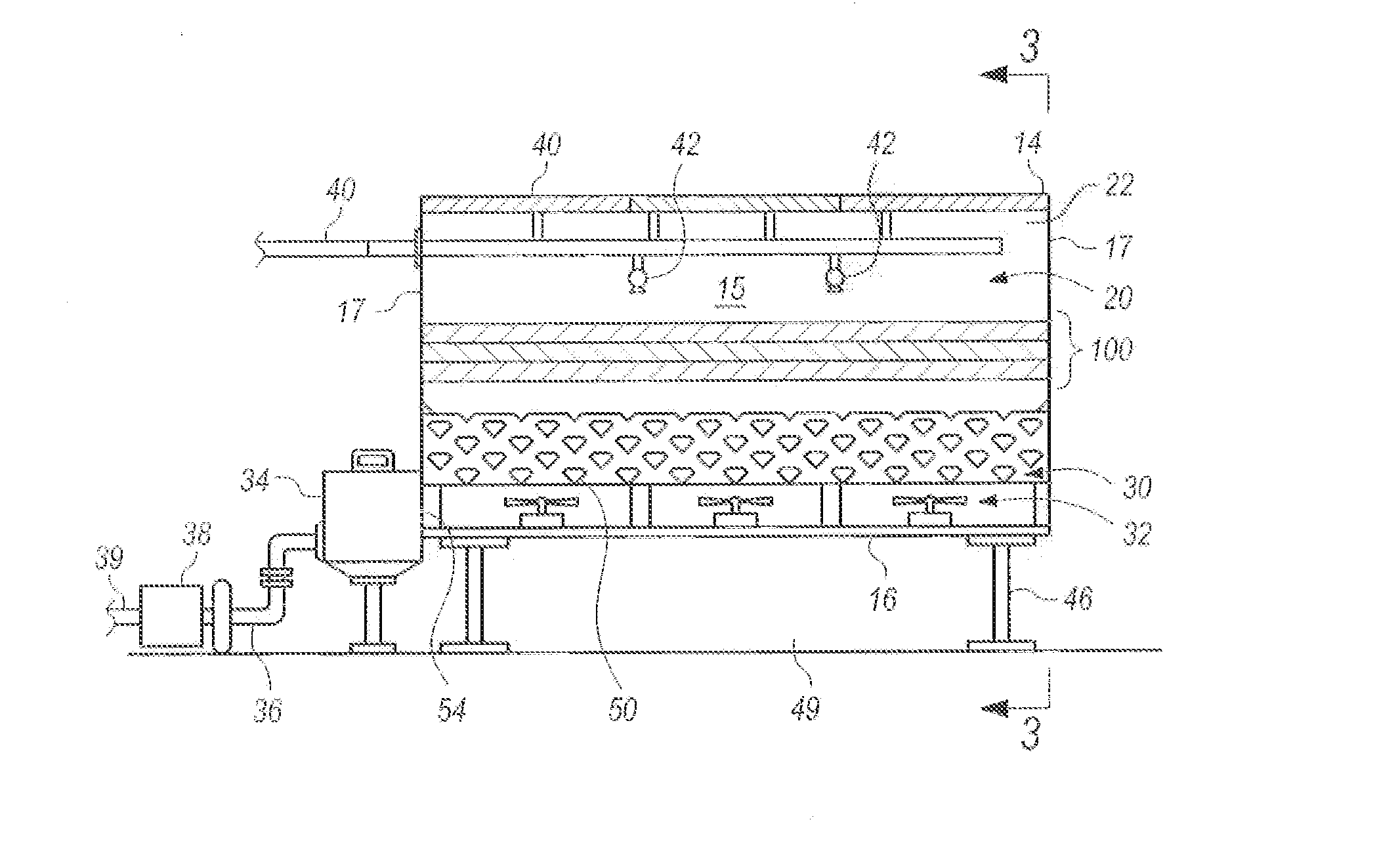
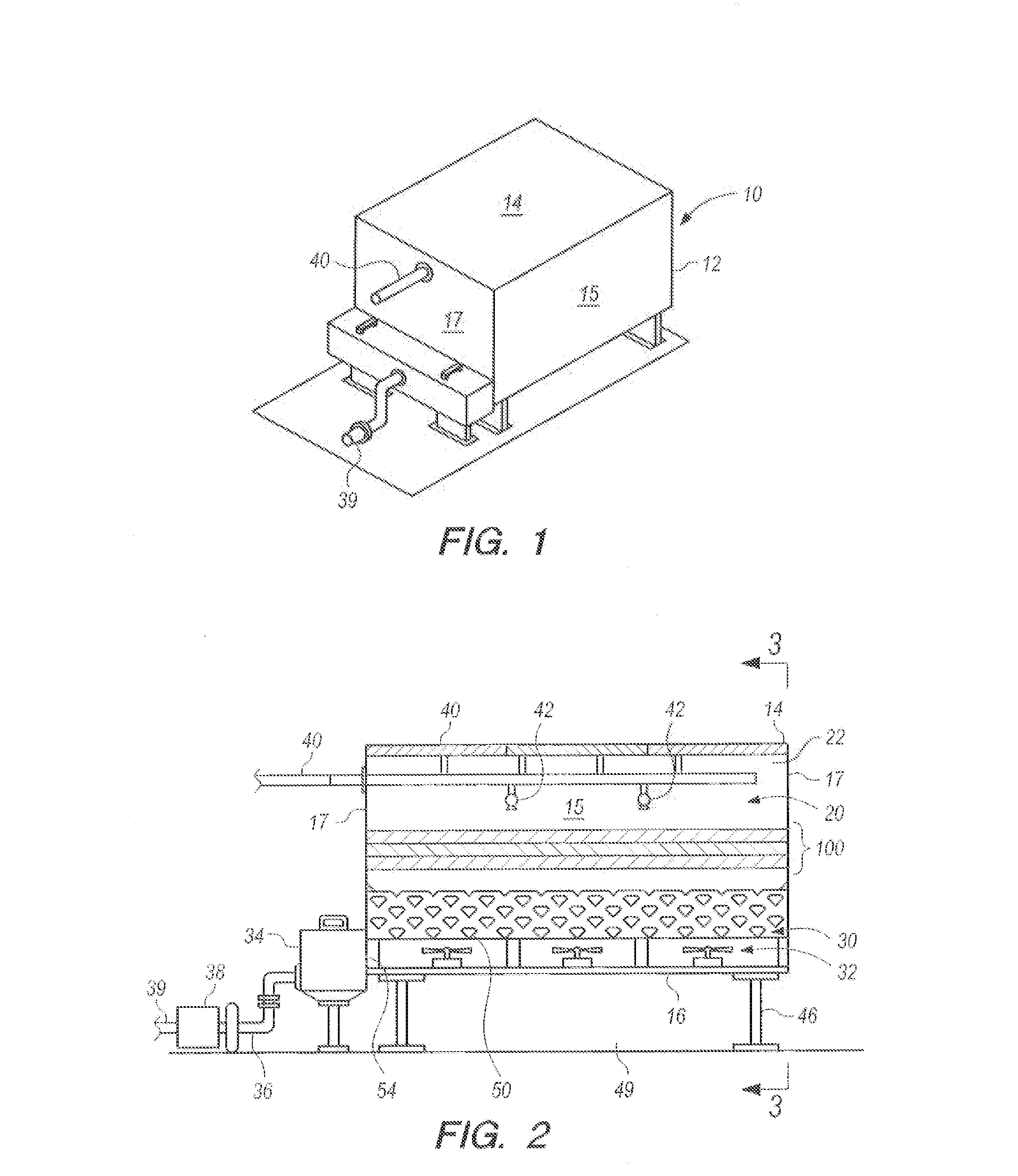
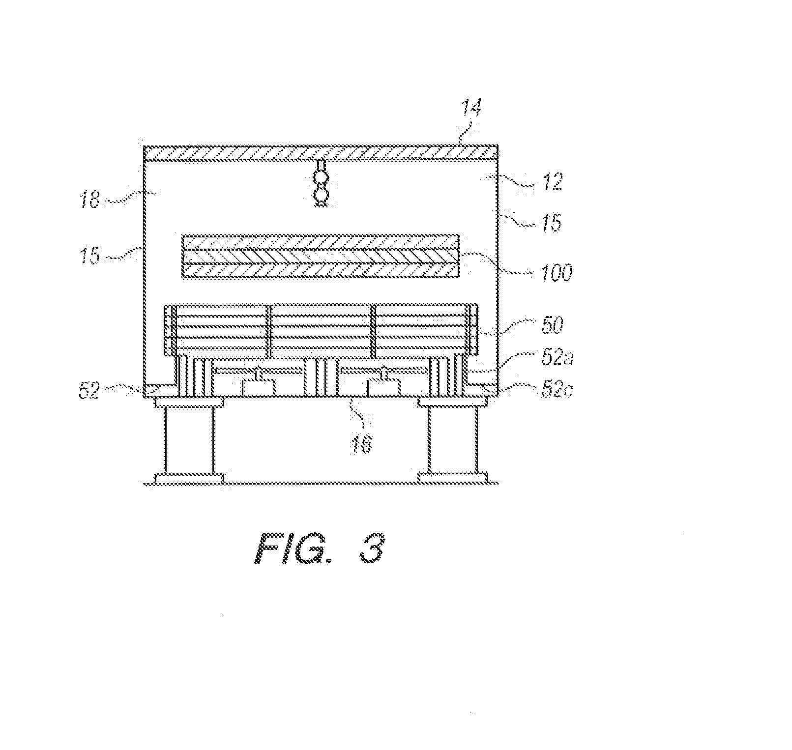
[0067]Referring now to the drawings in detail, and initially to FIG. 1, a direct draft cooling tower 10 as described in U.S. patent application Ser. No. 14 / 660,801 is illustrated. The cooling tower is designed to advantageously use the evaporation of water or other liquids to cool the liquids. The cooling tower includes an exterior housing 12 having an open top 14, vertical side walls 15, and end walls 17. As seen in FIG. 2, wherein a side wall 15 has been removed to illustrate the interior, housing 12 contains a liquid distribution system 20 at its upper end 22.

[0068]In an evaporative cooling tower as shown the liquid from distribution system 20 is passed countercurrent through an evaporative cooling media of well-known construction forming a layer 100 in the housing 12. The evaporative cooling media can take many forms, and typically could be cross-corrugated sheets of plastic material which form air passageways therebetween through which the liquid and air pass countercurrently. ...


PUM

PropertyMeasurementUnit
Lengthaaaaaaaaaa
Widthaaaaaaaaaa
Elevationaaaaaaaaaa

Abstract

A cooling tower is provided with a housing containing a fan at the bottom of the tower, and a plurality of layers of water collection troughs or channels above the fan to capture water droplets sprayed downwardly from the top of the device through an evaporative cooling pad located above the collection troughs. The collection troughs extend from one side of the housing to the other in the form of a structural support for the housing and the equipment therein. The troughs have open ends which extend through the housing to discharge collected water to an adjacent vertical tank.

Description

[0001]This application claims the benefit U.S. Provisional Application Nos. 61 / 208,995 filed Mar. 3, 2009; 61 / 217,822, filed Jun. 5, 2009; and 61 / 270,723 filed Jul. 13, 2009, and U.S. Provisional Application Nos. 62 / 125,943 and 62 / 125,941 filed Mar. 2, 2015 and is a continuation-in-part of U.S. patent application Ser. No. 14 / 660,871 filed Mar. 17, 2015 which is a divisional application of U.S. patent application Ser. No. 13 / 148,541 filed Sep. 13, 2011, which is a 371 of PCT / US 2010 / 024929 filed Feb. 22, 2010, the disclosures of which are incorporated herein by reference.BACKGROUND OF THE INVENTION[0002]The present invention relates generally to modular direct forced draft fluid cooling towers using an improved air diffusing water drainage collection system as a structural member in such cooling towers and which modular towers can be connected together for increased capacity.DESCRIPTION OF THE PRIOR ART[0003]Conventional types of industrial cooling towers include so-called counterflo...

Claims


Application Information

Patent Timeline
IPC IPC(8): F28C1/02F28F25/04
CPCF28F25/04F28C1/02F28F25/02F28D5/02Y10T137/8593F24F5/0035F28F25/00F28F25/10F28F2025/005Y02B30/54Y02B30/70F28C1/00F28C1/16
Inventor CURTIS, HAROLD DEAN
Owner SYNTECH TOWERS L L C
Why Eureka
Try Eureka