
Gas absorption spectroscopic system and gas absorption spectroscopic method

a spectroscopic system and gas absorption technology, applied in the field of gas absorption spectroscopic system, can solve the problems of measurement impossible, light with trace amount of energy decay in the intensity of light leakage to the outside of the mirror, etc., to minimize the pressure dependence of the measured temperature and accurate determination

Inactive Publication Date: 2015-11-26
REYNAERS ALUMINIUM NV +1
View PDF31 Cites 21 Cited by
  • Summary
  • Abstract
  • Description
  • Claims
  • Application Information

AI Technical Summary

Benefits of technology

The gas absorption spectroscopic system described in this patent allows for accurate determination of the wavelength of light sources by sweeping the wavelength at a high frequency. This system uses a mathematical operation based on wavelength information to achieve high-order synchronous detection with correct modulation depth, regardless of non-linearities in the power source. The system also allows for simultaneous acquisition of WMS spectra with multiple modulation depths, making it easier to realize a system with a single light source and minimize temperature dependency. In summary, the gas absorption spectroscopic system provides improved accuracy and efficiency in gas analysis.

Problems solved by technology

Meanwhile, light with a trace amount of energy leaks to the outside of the mirrors.
In this state, if the laser radiation is discontinued, the light energy in the resonator decays at a rate corresponding to the amount of light lost from the resonator, which simultaneously causes a decay in the intensity of light leaking to the outside of the mirrors.
Although this technique is more sensitive than WMS, it is susceptible to the contamination of the resonator, and furthermore, its dynamic range is generally narrow, since the resonator loss rapidly increases with an increase in the amount of absorption, making the measurement impossible.

Method used


Image

  • Gas absorption spectroscopic system and gas absorption spectroscopic method
  • Gas absorption spectroscopic system and gas absorption spectroscopic method
  • Gas absorption spectroscopic system and gas absorption spectroscopic method

Examples


Embodiment Construction

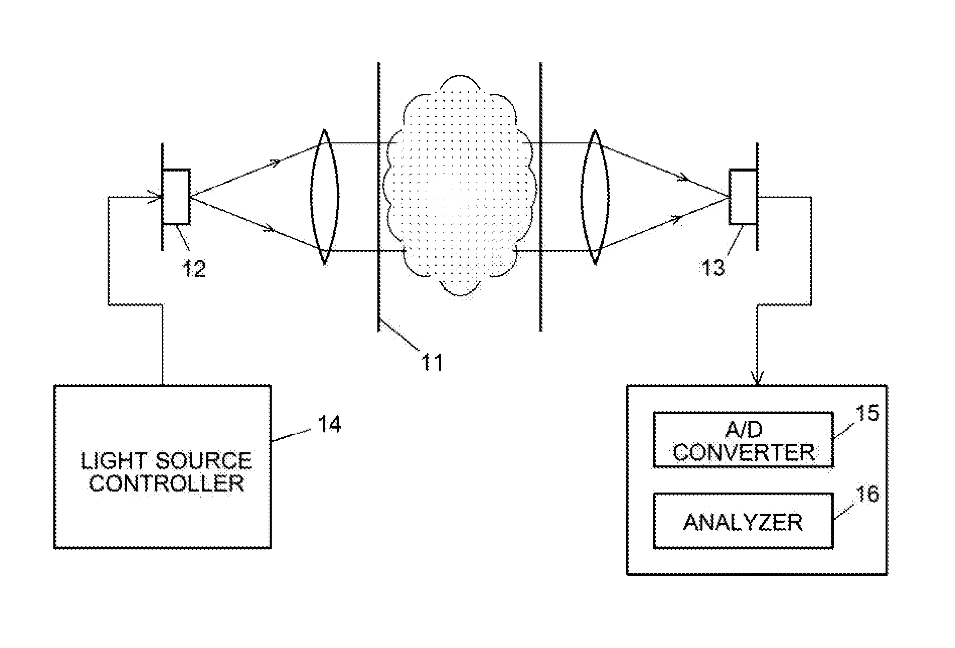
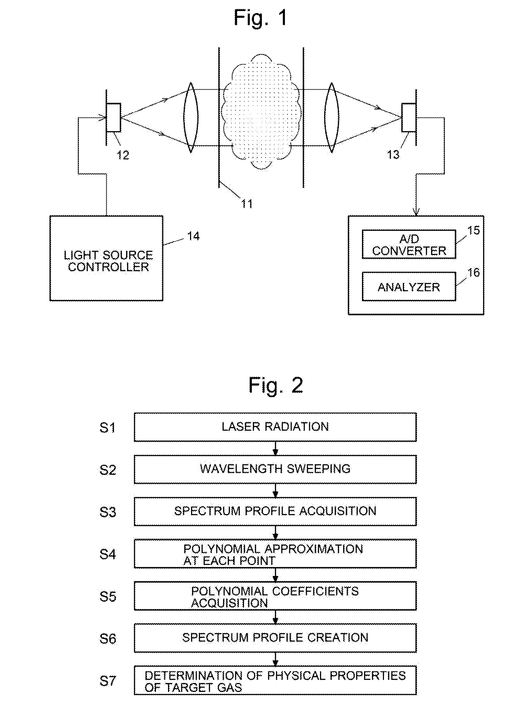
[0048]A schematic configuration of a gas absorption spectroscopic system as one embodiment of the present invention is shown in FIG. 1. A laser source 12 and a photodetector 13 are placed on both sides of a gas cell 11 which contains target gas or through which the target gas is passed. The laser source 12 has a variable wavelength. A light source controller 14 sweeps (varies) this wavelength between the shortest and longest predetermined wavelengths. The photodetector 13 produces an electric signal which shows the intensity of light. This signal is subjected to digital sampling by an A / D converter 15 and sent to an analyzer 16.

[0049]A procedure for measuring the concentration, temperature, pressure and other properties of the target gas is as follows (FIG. 2): The light source controller 14 operates the laser source 12 to radiate laser light having the shortest predetermined wavelength (Step S1) and then sequentially varies the wavelength to the longest wavelength (Step S2). As alr...


PUM

PropertyMeasurementUnit
gas absorption spectroscopicaaaaaaaaaa
wavelengthaaaaaaaaaa
temperatureaaaaaaaaaa

Abstract

Provided is a gas absorption spectroscopic system and gas absorption spectroscopic method capable of accurately measuring the concentration or other properties of gas even in high-speed measurements. Laser light with a varying wavelength is cast into target gas. A spectrum profile representing a change in the intensity of the laser light transmitted through the target gas with respect to wavelength is determined. For this spectrum profile, polynomial approximation is performed at each wavelength point within a predetermined wavelength width, using an approximate polynomial. Based on the coefficients of the terms in the approximate polynomial at each point, an nth order derivative curve, where n is an integer of zero or larger, of the spectrum profile is created. A physical quantity of the target gas is determined based on the thus created nth order derivative curve.

Description

TECHNICAL FIELD[0001]The present invention relates to a gas absorption spectroscopic system and method for measuring the concentration, temperature, pressure and other properties of target gas, based on a laser light absorption spectrum of the gas. The gas absorption spectroscopic system and method can be applied for contactless high-speed measurement of the concentration, temperature and pressure of gas in the automotive industry. It can also be used for a measurement of combustion gas within a plant furnace or similar gas in high-temperature and high-pressure environments, as well as in various other areas.BACKGROUND ART[0002]There are three kinds of gas absorption spectroscopy using lasers:[0003](1) DLAS (Direct Laser Absorption Spectroscopy)[0004](2) WMS (Wavelength Modulated Spectroscopy)[0005](3) CRDS (Cavity Ring Down Spectroscopy)[0006]In DLAS, laser light is cast into target gas and detected with a photodetector. In this detection, the wavelength of the laser light cast int...

Claims


Application Information

Patent Timeline
Patent Type & Authority Applications(United States)
IPC IPC(8): G01N21/39G01N21/31
CPCG01N21/39G01N2201/0612G01N21/3103G01J3/42G01N21/3504G01J3/027G01J3/10G01J3/4338
Inventor MURAMATSU, TAKASHIMORIYA, NAOJIMATSUDA, NAOKI
Owner REYNAERS ALUMINIUM NV
Learn More