Compact gantry system using independently controllable detectors

a gantry system and detector technology, applied in the field of medical imaging systems, can solve the problems of limiting the application of the scanner to a particular type of scan, sensitivity of imaging, size, cost, etc., and achieve the effects of reducing the number of scans

Active Publication Date: 2015-12-03
GENERAL ELECTRIC CO
View PDF3 Cites 9 Cited by
  • Summary
  • Abstract
  • Description
  • Claims
  • Application Information

AI Technical Summary

Benefits of technology

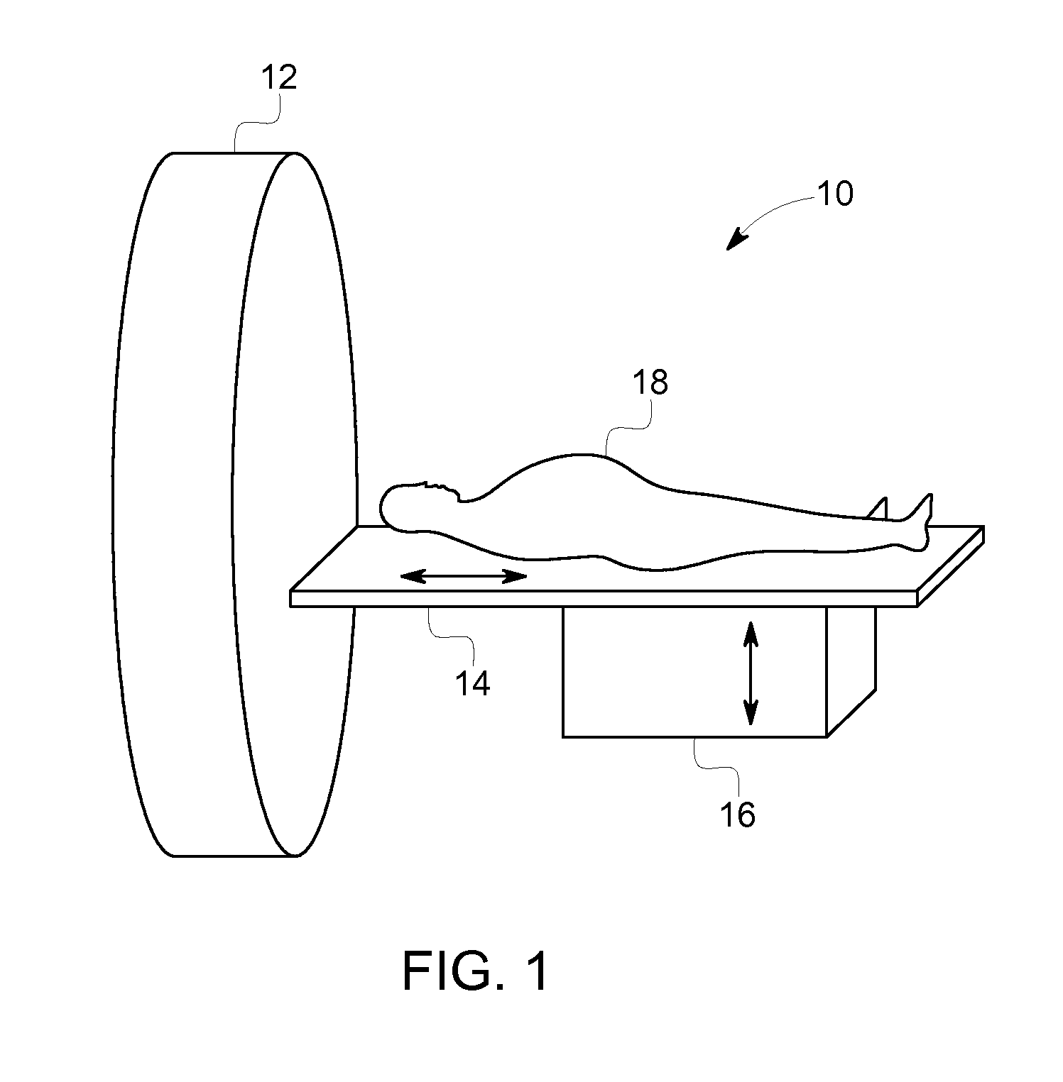
[0005]There is a need for gantry systems to be compact to provide a positive patient experience. There is a need for gantry systems to support various imaging configurations to provide flexibility, speed, and cost savings.

Problems solved by technology

In the selection of material, tradeoffs must be made, such as imaging sensitivity, size, cost, etc.
Additionally, specific collimation may be provided, which typically limits the application of the scanner to a particular type of scan, such as whole body bone exams, cardiac exams, among other types of scans.

Method used


Image

  • Compact gantry system using independently controllable detectors
  • Compact gantry system using independently controllable detectors
  • Compact gantry system using independently controllable detectors

Examples


Embodiment Construction

[0025]The foregoing summary, as well as the following detailed description of certain embodiments and claims, will be better understood when read in conjunction with the appended drawings. To the extent that the figures illustrate diagrams of the functional blocks of various embodiments, the functional blocks are not necessarily indicative of the division between hardware circuitry. Thus, for example, one or more of the functional blocks (e.g., processors, controllers or memories) may be implemented in a single piece of hardware (e.g., a general purpose signal processor or random access memory, hard disk, or the like) or multiple pieces of hardware. Similarly, the programs may be stand alone programs, may be incorporated as subroutines in an operating system, may be functions in an installed software package, and the like. It should be understood that the various embodiments are not limited to the arrangements and instrumentality shown in the drawings.

[0026]As used herein, an elemen...


PUM


Abstract

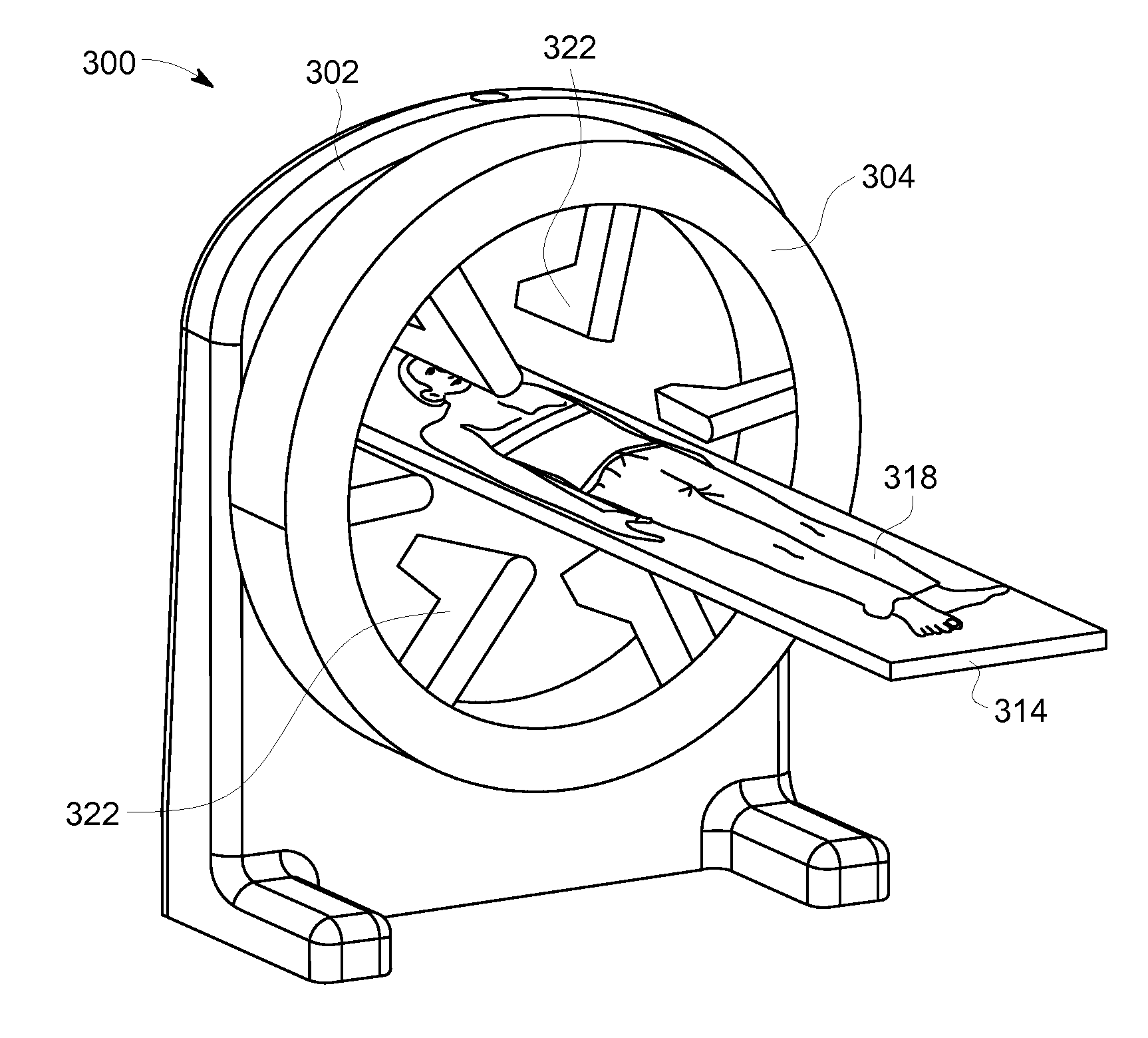
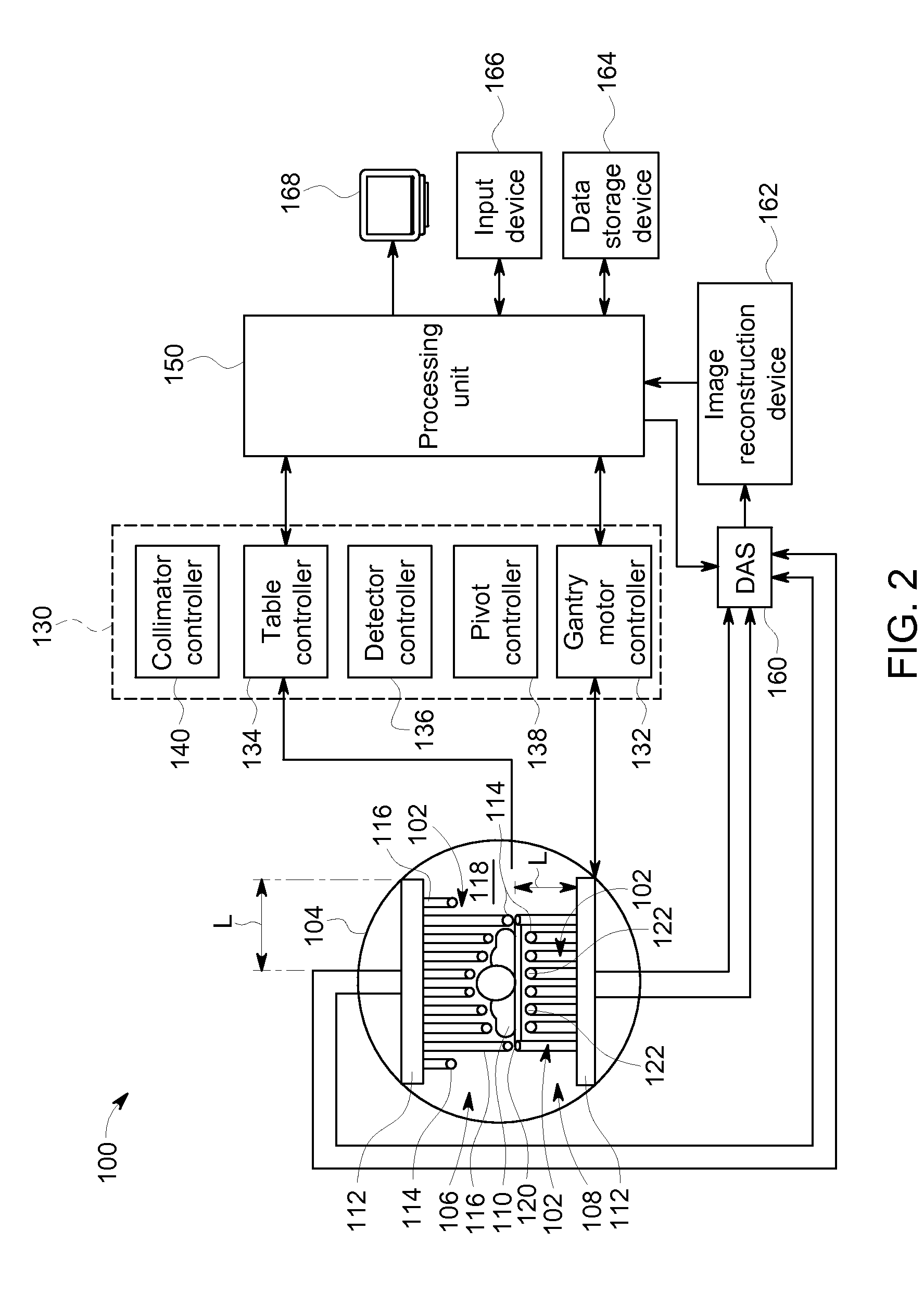
A gantry system is provided. The gantry system may be used for acquiring image data and reconstructing the image data into output images. Image detectors include a detector arm and detector head. Image detectors are attached to a gantry in a compact configuration such that the image detector head may extend into the bore of a stator. The system can be a Nuclear Medicine (NM) imaging system to acquire Single Photon Emission Computed Tomography (SPECT) image information.

Description

PRIORITY AND REFERENCE TO RELATED APPLICATIONS[0001]This application is a continuation-in-part of U.S. patent application Ser. No. 14 / 612,398, entitled “IMAGING SYSTEM USING INDEPENDENTLY CONTROLLABLE DETECTORS”, filed Feb. 3, 2015, which is a continuation of U.S. patent application Ser. No. 14 / 135,751, entitled “IMAGING SYSTEM USING INDEPENDENTLY CONTROLLABLE DETECTORS”, filed Dec. 20, 2013 and patented on May 12, 2015 as U.S. Pat. No. 9,029,791, the disclosures of which is incorporated by reference herein as if set forth in their entirety.BACKGROUND[0002]The subject matter disclosed herein relates generally to medical imaging systems, and more particularly to Nuclear Medicine (NM) imaging systems which can be Single Photon Emission Computed Tomography (SPECT) imaging systems.[0003]In NM imaging, such as SPECT imaging, radiopharmaceuticals are administered internally to a patient. Detectors (e.g., gamma cameras), typically installed on a gantry, capture the radiation emitted by the...

Claims


Application Information

Patent Timeline
Patent Type & Authority Applications(United States)
IPC IPC(8): A61B6/03G01T1/29G01T1/161
CPCA61B6/037G01T1/2985G01T1/161A61B6/0407A61B6/4258A61B6/4266A61B6/503A61B6/5205A61B6/545A61B6/547G01T1/1648G06T11/005
Inventor KHEN, ROEEBOUHNIK, JEAN-PAUL
Owner GENERAL ELECTRIC CO
Why Eureka
Try Eureka