

Sensor tag and manufacturing method for sensor tag
a technology of sensor tags and manufacturing methods, applied in the field of sensor tags, can solve problems such as errors generated in the temperature measurement results produced by measurement devices, and achieve the effect of suppressing the effect of variations in the characteristics of resonators and measuring accurately
- Summary
- Abstract
- Description
- Claims
- Application Information
AI Technical Summary
Benefits of technology
Problems solved by technology
Method used
Image

Examples
first embodiment
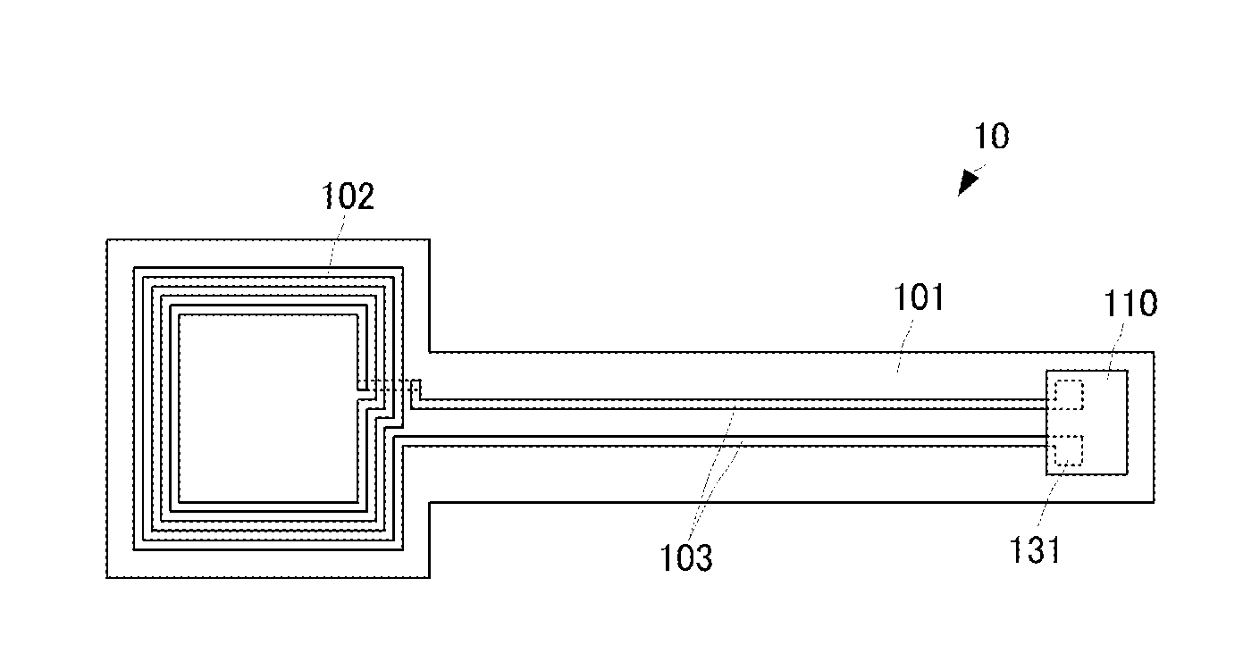
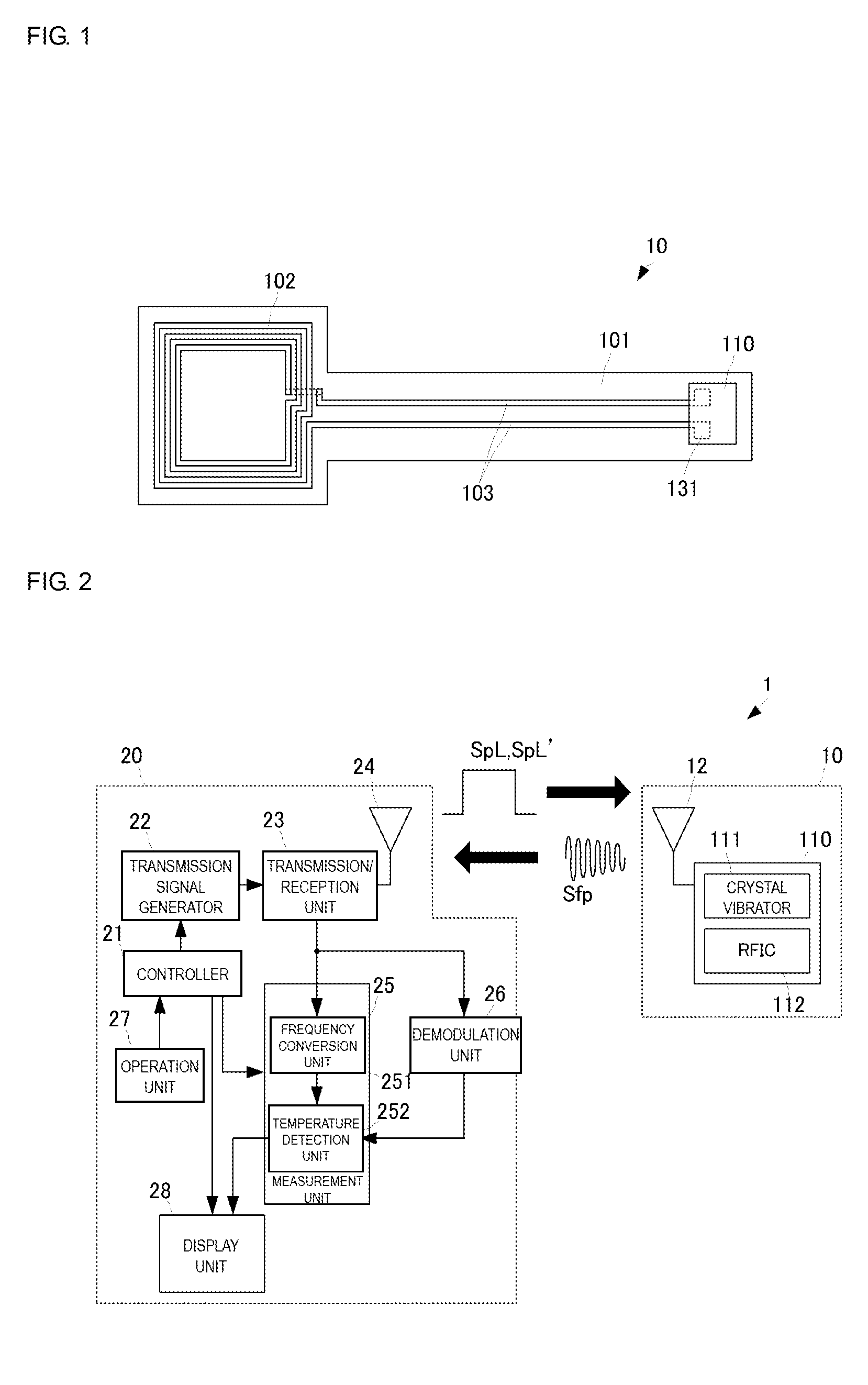
[0068]The above-described temperature measurement system is one example that realizes the operational effect of the disclosure of the present application. The operational effect of the disclosure of the present application can be obtained as with the above-described configuration by using a configuration that realizes the following method. FIG. 6 is a flowchart of a temperature measurement method according to the present disclosure.
[0069]The temperature measurement device 20 generates the excitation signal SpL′ (S101) and transmits (radiates) the excitation signal SpL′ (S102). The temperature measurement device 20 switches to a reception mode (S103) after transmitting the excitation signal SpL′.
[0070]The sensor tag 10 receives the excitation signal SpL′ (S201). The RFIC 112 is activated by the excitation signal SpL′ (S202). The RFIC 112 reads out the equivalent circuit constant information and transmits (radiates) a response signal including the equivalent circuit constant informati...
second embodiment
[0080]The thus-configured sensor tag 10A is employed in a temperature measurement system 1A as illustrated in FIG. 8. FIG. 8 is a configuration diagram of a temperature measurement system including the sensor tag according to the present disclosure.
[0081]A temperature measurement device 20A of the temperature measurement system 1A of this embodiment also has the same basic configuration as the temperature measurement device 20 described in the first embodiment. Hereafter, only parts different to the temperature measurement device 20 according to the first embodiment will be described in detail.
[0082]The temperature measurement device 20A includes an information reading unit 29. The information reading unit 29 is composed of a CCD camera or a barcode reader for example and reads out the equivalent circuit constant information recorded in the information recording mark 140. The information reading unit 29 outputs the equivalent circuit constant information to the temperature detection...
third embodiment
[0085]A sensor tag and a sensor tag manufacturing method will be described with reference to the drawings.
[0086]FIG. 9 is a flowchart illustrating the sensor tag manufacturing method according to the third embodiment of the present disclosure. FIGS. 10A and 10B are partial plan views illustrating example forms of a plurality of types of antennas.
[0087]In the sensor tag manufacturing method of this embodiment, first, a plurality of types of antennas having different inductances are prepared (S301). For example, as illustrated in FIGS. 10A and 10B, antennas having different numbers of turns are prepared. In the example of FIGS. 10A and 10B, the number of turns of an antenna 102A is smaller than the number of turns of an antenna 102B. Therefore, an inductance LanA of the antenna 102A is smaller than an inductance LanB of the antenna 102B. Here, the connection conductors 103 have the same shape for the respective antennas. In FIGS. 10A and 10B, an example of two types of antenna is ill...
PUM
| Property | Measurement | Unit |
|---|---|---|
| thickness | aaaaa | aaaaa |
| physical quantity | aaaaa | aaaaa |
| equivalent inductance | aaaaa | aaaaa |
Abstract
Description
Claims
Application Information