Automotive radar sub-system packaging for robustness

Active Publication Date: 2015-12-03
TOYOTA JIDOSHA KK
View PDF12 Cites 22 Cited by
  • Summary
  • Abstract
  • Description
  • Claims
  • Application Information

AI Technical Summary

Benefits of technology

The patent describes a method for packaging a vehicle radar unit and a design of the radar unit itself. The technical effects of the patent include improved signal transmission and reduced latency in processing transmitted and received signals. The design also provides for efficient use of space and reduced interference between components. These improvements can lead to improved performance and reliability of the vehicle radar unit.

Problems solved by technology

RFIC devices are very sensitive to, for example, dust, dirt, and other environmental exposure.
However, manufacturing an entire radar system in a clean room may be cost prohibitive.
However, with the RFIC device being positioned in a sealed environment, many problems may arise.
For example, communications with both circuits may be difficult (e.g., signal loss may be large, placement of through vias may be difficult, etc.); performance of the RFIC device is reduced; it may not be possible to manufacture and assemble the RFIC device to the sub-system in a clean environment; if the RFIC device is manufactured in a clean room, the entire module may be required to be manufactured in a clean room (increased cost); and any combination of the above problems.

Method used


Image

  • Automotive radar sub-system packaging for robustness
  • Automotive radar sub-system packaging for robustness
  • Automotive radar sub-system packaging for robustness

Examples


Embodiment Construction

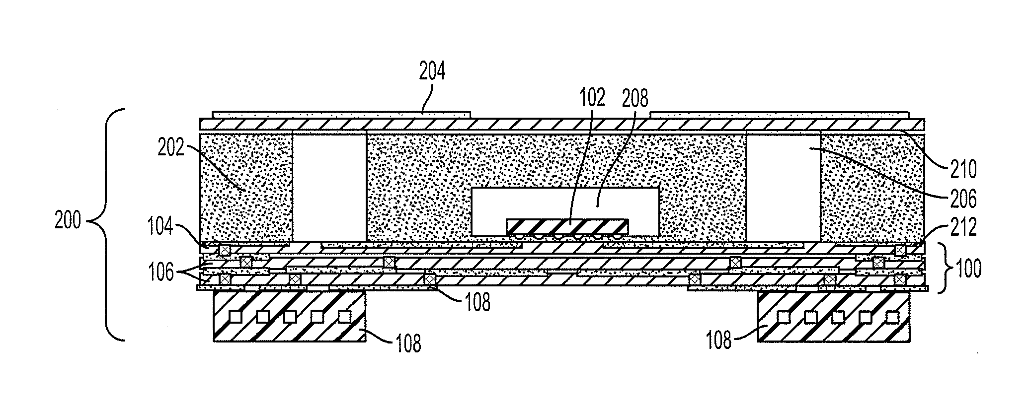
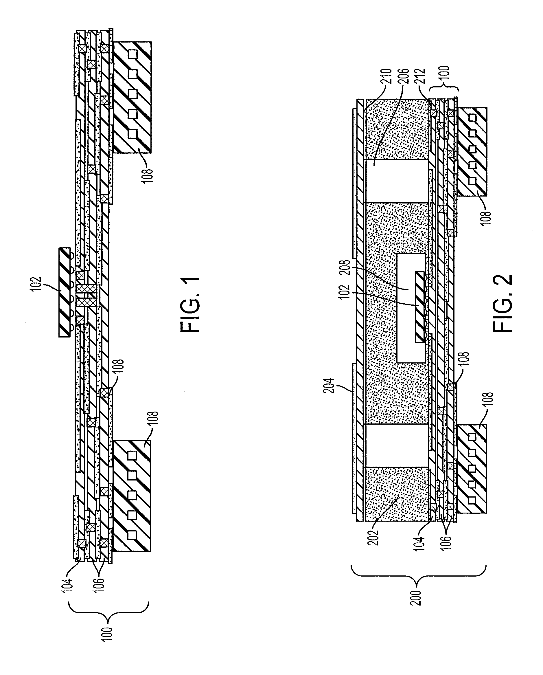
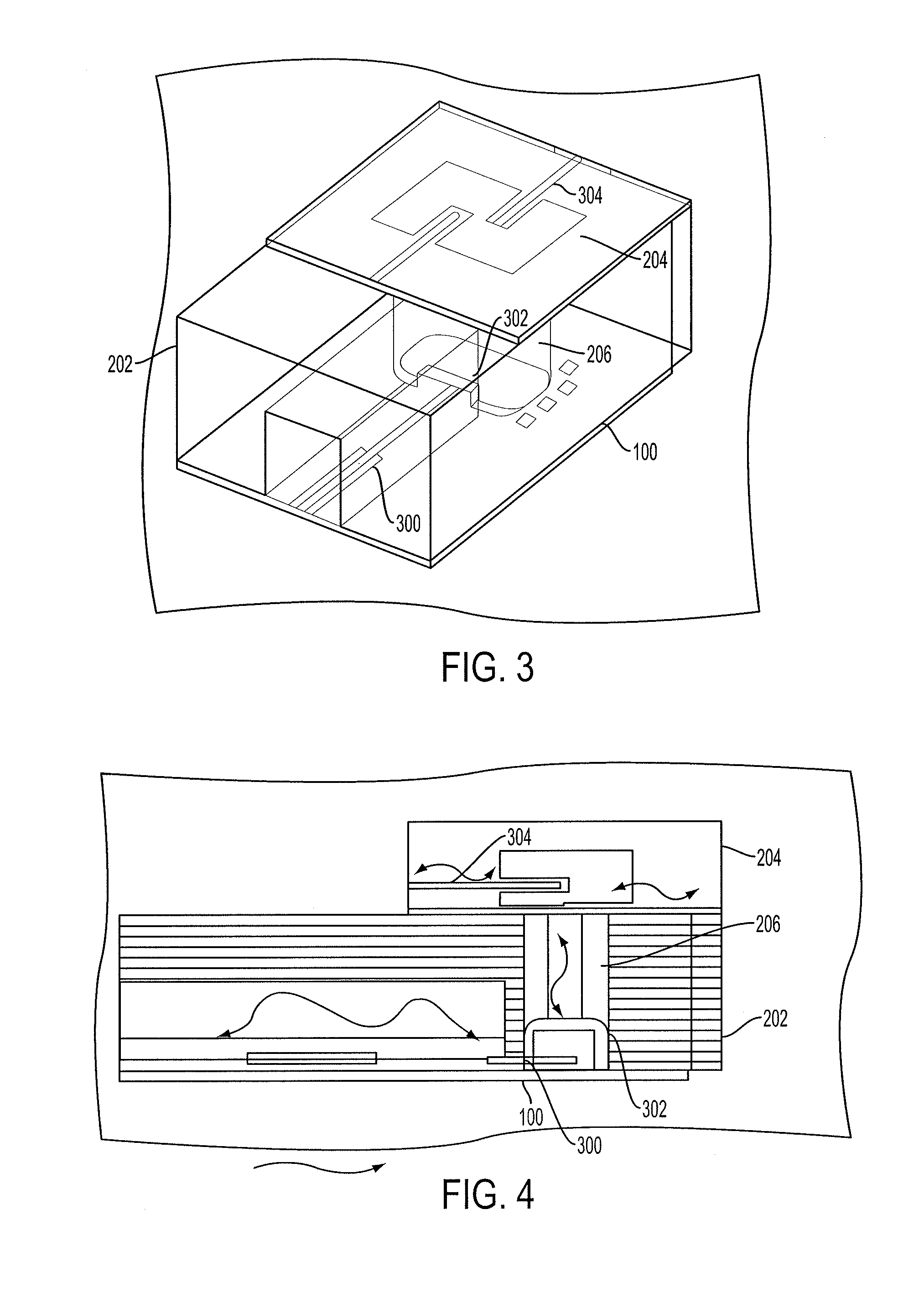
[0021]Apparatus, systems and methods that implement the embodiments of the various features of the invention will now be described with reference to the drawings. The drawings and the associated descriptions are provided to illustrate some embodiments of the invention and not to limit the scope of the invention. Throughout the drawings, reference numbers are re-used to indicate correspondence between referenced elements. For purposes of this disclosure, when mentioned, a connection may be a wired connection, a wireless connection, or a mix of wired and wireless connections. A connection also provides for communications propagating both ways along the connection. For example, a connection with a processor provides for the processor to receive communications and to transmit communications over the connection.

[0022]The methods, systems and devices disclosed within provide several key advantages over the state of the art. For example, a vehicular radar sub-system disclosed within can be...


PUM

PropertyMeasurementUnit
Frequencyaaaaaaaaaa
Electrical conductoraaaaaaaaaa
Exposure limitaaaaaaaaaa

Abstract

An integrated circuit for processing transmitted and received signals is positioned on a first printed circuit board. A second printed circuit board is provided which has a plurality of antenna elements and at least one transmission line. The first printed circuit board is bonded to a first side of a metal housing and the second printed circuit board is bonded to a second side of the metal housing, so that the integrated circuit is sealed from environmental exposure between the first printed circuit board and the metal housing. A waveguide chamber is provided and is located between the first printed circuit board and the second printed circuit board. A signal is allowed to propagate from the integrated circuit to the metal trace to the square metal section to the waveguide chamber to the at leas one transmission line to the plurality of antenna elements.

Description

BACKGROUND[0001]1. Field[0002]The invention relates to sub-systems of automotive radar and methods of manufacturing the same. More particularly, the invention relates to a radar sub-system module which houses a Radio Frequency Integrated Circuit (RFIC) and a waveguide signal transition through which the RFIC may communicate with an antenna array.[0003]2. Description of the Related Art[0004]Automotive radar systems are currently being provided in many automobiles. Over the past few years, automotive radar systems have been used with intelligent cruise control systems to sense and adjust the automobile's speed depending on traffic conditions. Today, automotive radar systems are being used with active safety systems to monitor the surroundings of an automobile for collision avoidance. Current automotive radar systems are divided into long range (for adaptive cruise control and collision warning) and short range (for pre-crash, collision mitigation, parking aid, blind spot detection, et...

Claims


Application Information

Patent Timeline
IPC IPC(8): G01S7/02G01S13/02G01S13/931
CPCG01S7/02Y10T29/49004G01S13/02G01S13/931H01Q1/3233H01Q13/206H01Q21/065H05K1/144H05K2201/10098H01L2223/6677H01L2224/16227H01L2224/16235G01S7/027
Inventor SCHMALENBERG, PAUL D.LEE, JAE SEUNG
Owner TOYOTA JIDOSHA KK
Why Eureka
Try Eureka