Diffraction grating for laser pulse compression and laser device

a laser and pulse compression technology, applied in the direction of laser details, instruments, electrical equipment, etc., can solve the problems of increasing the production cost of diffraction gratings, imposing a considerable restriction, and damage to the grating surface (i.e. the reflecting surface) of diffraction gratings, and achieves high damage threshold, high diffraction efficiency, and high power.

Inactive Publication Date: 2015-12-03
SHIMADZU CORP
View PDF6 Cites 8 Cited by
  • Summary
  • Abstract
  • Description
  • Claims
  • Application Information

AI Technical Summary

Benefits of technology

[0023]With the diffraction grating for laser pulse compression according to the present invention, it is possible to ensure a high level of damage threshold and achieve a high diffraction efficiency for the required wavelength without using a special structure, such as a multilayer dielectric film. Therefore, by using the diffraction grating according to the present invention as a pulse compressor in a laser device using the CPA method, a high level of power can be realized while reducing the device cost.
[0024]In the first and second modes of the laser device according to the present invention, the previously described diffraction grating for laser pulse compression according to the present invention is used as the diffraction grating which receives the highest amount of light energy on its grating surface (reflecting surface) in the pulse compressor, and the laser pulse impinges on this grating surface of the diffraction grating at substantially right angles, so that the grating surface is highly durable and less likely to undergo damage. Therefore, for example, it is possible to increase the degree of amplification in a laser amplifier or to reduce the spatial spread of the beam produced by the diffraction grating, so as to increase the intensity of the laser pulse to be eventually extracted from the pulse compressor.

Problems solved by technology

Therefore, the damage to the grating surfaces (i.e. reflecting surfaces) of the diffraction gratings will be a problem.
This means that the damage threshold (i.e. energy tolerance) of the diffraction gratings used in the pulse compressor imposes a considerable restriction in realizing a high-power laser device using the CPA method.
However, those techniques increase the production cost of the diffraction gratings and make the laser device more expensive.

Method used


Image

  • Diffraction grating for laser pulse compression and laser device
  • Diffraction grating for laser pulse compression and laser device
  • Diffraction grating for laser pulse compression and laser device

Examples


Embodiment Construction

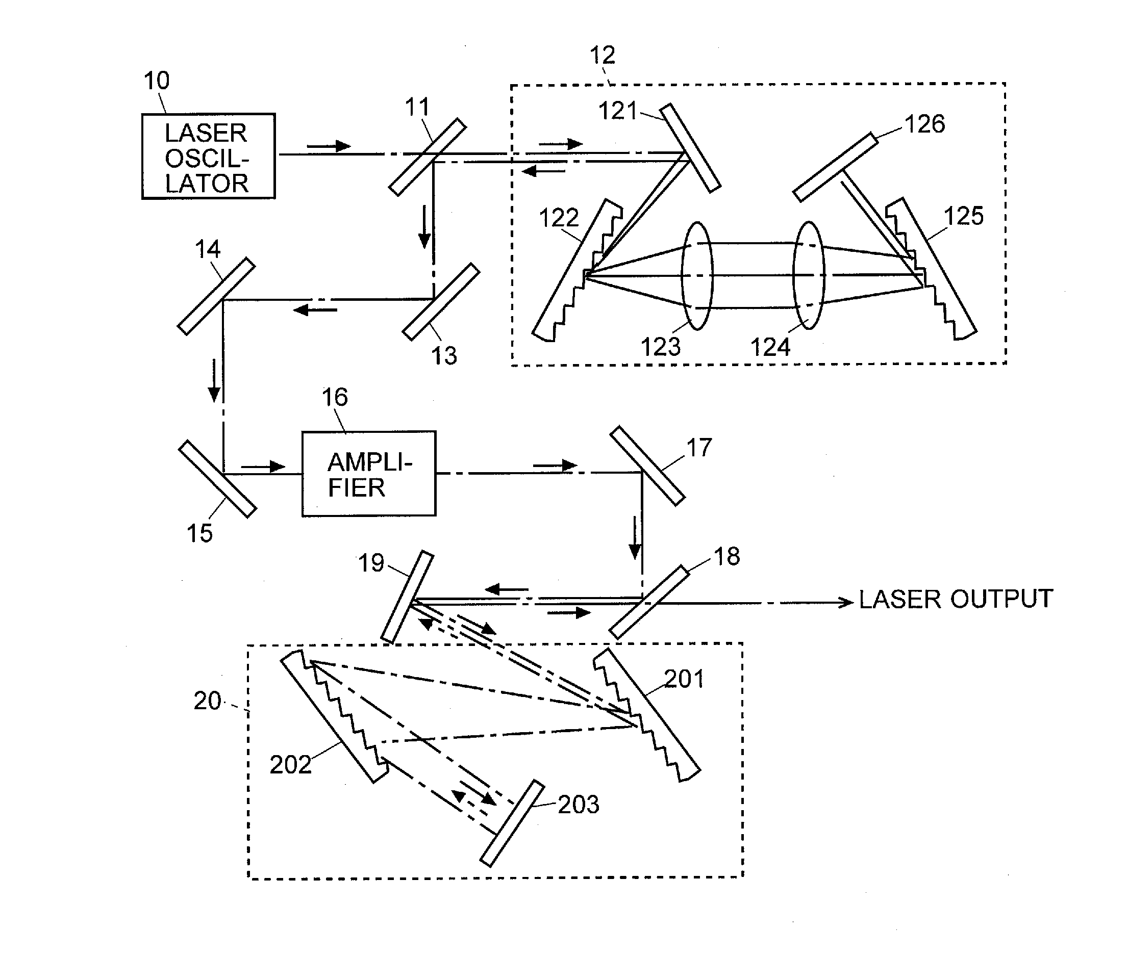
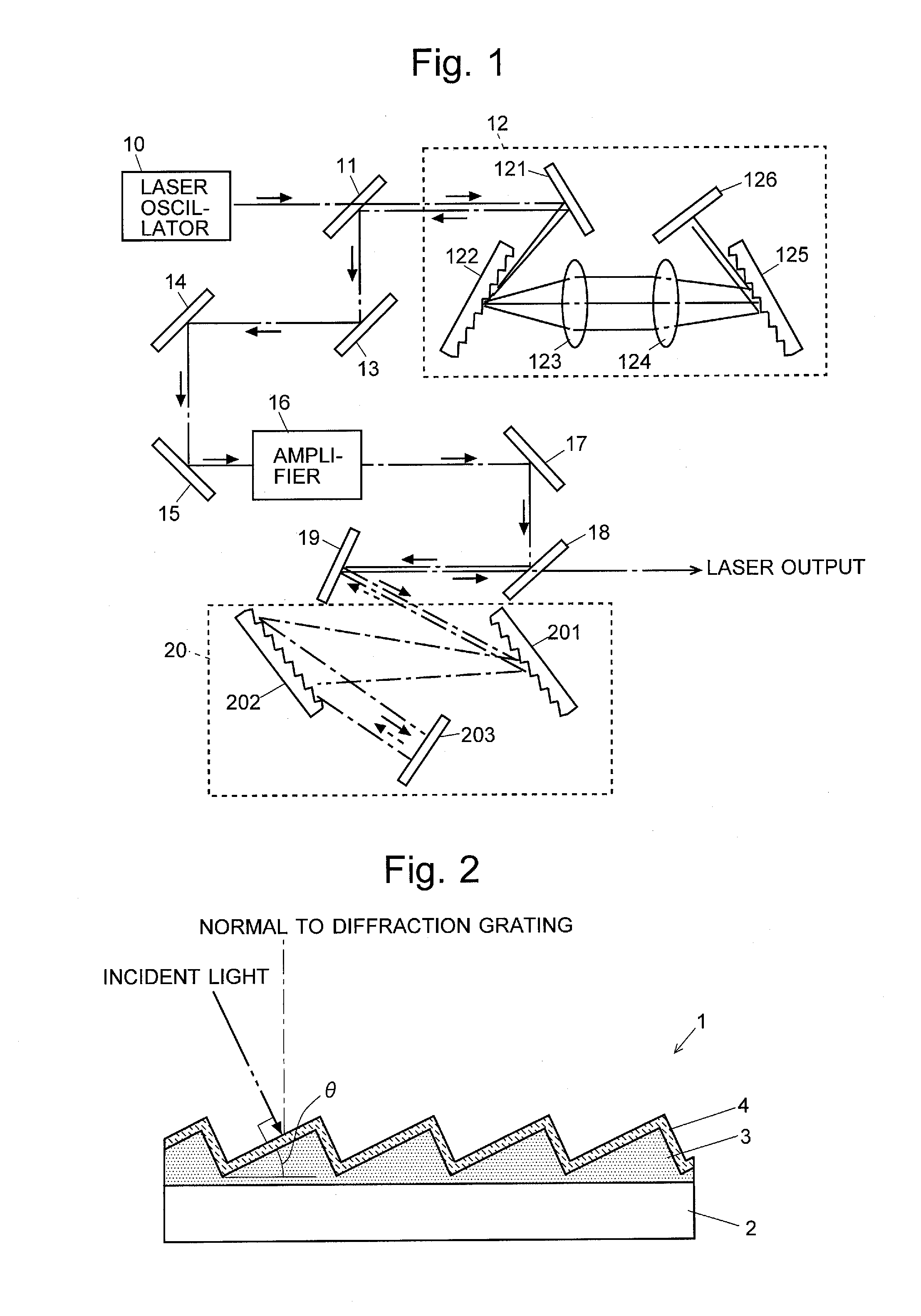
[0031]A diffraction grating according to one embodiment of the present invention as well as a laser device using this grating is hereinafter described with reference to the attached drawings. FIG. 1 is an overall configuration diagram of the laser device of the present embodiment.

[0032]In the laser device of the present embodiment, a laser oscillator 10 produces a laser pulse having an extremely short duration around a predetermined wavelength. This pulse is introduced via a half mirror 11 into a pulse stretcher 12. The pulse stretcher 12 returns the same laser pulse after increasing its pulse width to the half mirror 11. This laser pulse is the chirped pulse, whose peak intensity (power) is decreased by an amount corresponding to the increase in the pulse width. The chirped pulse is reflected by the half mirror 11 as well as the mirrors 13, 14 and 15, and introduced into a laser amplifier 16. In the laser amplifier 16, the pulse is amplified to obtain a pulse having an increased pe...


PUM


Abstract

A pulse compressor for compressing a laser pulse in a laser device using a chirped pulse amplification method includes two identically shaped diffraction gratings arranged parallel to each other with their respective grating surfaces facing each other and a total reflection mirror for receiving a laser pulse through the diffraction grating and returning it back to the same gratings. Each diffraction grating is a reflective blazed diffraction grating having grooves with a sawtooth-shaped section covered with a reflective Au coating on their surface, with the blaze angle determined so that, at the wavelength of the laser pulse to be used, the incident angle of a laser pulse entering the pulse compressor and first order diffracted light form a relationship of mirror reflection with the groove slope and so that a predetermined level of diffraction efficiency is obtained. Since the laser pulse impinges on the grating at substantially right angles to the groove slope, a high level of damage threshold is obtained and a high-power laser pulse can be generated.

Description

TECHNICAL FIELD[0001]The present invention relates to a diffraction grating for laser pulse compression used in a pulse compressor for compressing the pulse width of a laser pulse as well as a laser device in which this diffraction grating is used in a pulse compressor.BACKGROUND ART[0002]As a laser device for generating the so-called femtosecond laser which is high-powered (high-energy) laser light having a pulse width on the order of femtoseconds to picoseconds, a laser device using a chirped pulse amplification (CPA) method is commonly known (for example, see Patent Literature 1). In a laser device using the CPA method, the duration (pulse width) of the laser light generated by a laser oscillator is increased by a laser stretcher to reduce its peak intensity, after which its power is amplified by a laser amplifier to such an extent that the laser medium will not be damaged. Subsequently, the laser pulse is sent into a pulse compressor which works opposite to the pulse stretcher a...

Claims


Application Information

Patent Timeline
Patent Type & Authority Applications(United States)
IPC IPC(8): H01S3/00G02B5/18
CPCG02B5/1861H01S3/0057G02B5/1809H01S3/2308
Inventor OUE, YUKIMAKINO, YOSHITAKA
Owner SHIMADZU CORP
Why Eureka
Try Eureka