
Method and device for measuring venous blood oxygenation

a technology of venous blood oxygenation and measurement method, which is applied in the field of monitoring vital functions of the human body, can solve the problems of increased blood volume, difficulty in using methods by physicians, and obstruction of the vena caval, and achieve the effect of facilitating light delivery

Active Publication Date: 2015-12-10
MESPERE LIFESCI
View PDF10 Cites 7 Cited by
  • Summary
  • Abstract
  • Description
  • Claims
  • Application Information

AI Technical Summary

Benefits of technology

The patent is about a device that can deliver light to a patient's external tissue near their jugular vein and collect the light that is reflected or transmitted through that tissue. The device has a probe that helps with this process. The technical effect of this patent is a more precise and targeted way to deliver light to external tissue near a specific area, like the jugular vein, which can be useful in medical procedures.

Problems solved by technology

It may also result from vena caval obstruction and, at times, an increased blood volume.
The venous pressure is measured by a ruler as the vertical distance from the top of the oscillating venous column, to the level of the sternal angle plus vertical distance to the right atrium Due to the fact that the venous pulse is in generally very small, and due to complications with patients, this method is challenging for physicians to use and provides approximate values only.
As this technology is highly invasive, complicated, and expensive, many new methods have been developed in an attempt to replace it, but none have so far gained acceptance.
This method shows a lack of agreement between thermodilution and CO2-rebreathing cardiac output as described in Nielsson et al [12], due to unknown ventilation / perfusion inequality in patients.
Studies have been reported with mostly poor results, but in some exceptional cases, there was good correlation with a reference method.
Because of the highly scattering nature of tissue to the visible and near infrared light (400 nm-1000 nm), it is difficult to apply diffuse optical spectroscopy non-invasively to select blood vessels within a tissue to calculate blood oxygenation.
None of the above-mentioned techniques of measuring cardiac output combines all of the eight “Jansen” criteria mentioned above and, thus, none can displace the conventional thermodilution technique as described by Jansen et al [18].
Although highly invasive, complicated and expensive, the conventional thermodilution method remains the method of choice for measuring cardiac output.

Method used


Image

  • Method and device for measuring venous blood oxygenation
  • Method and device for measuring venous blood oxygenation
  • Method and device for measuring venous blood oxygenation

Examples


example 1

Measurement of Venous Pulse in a Patient

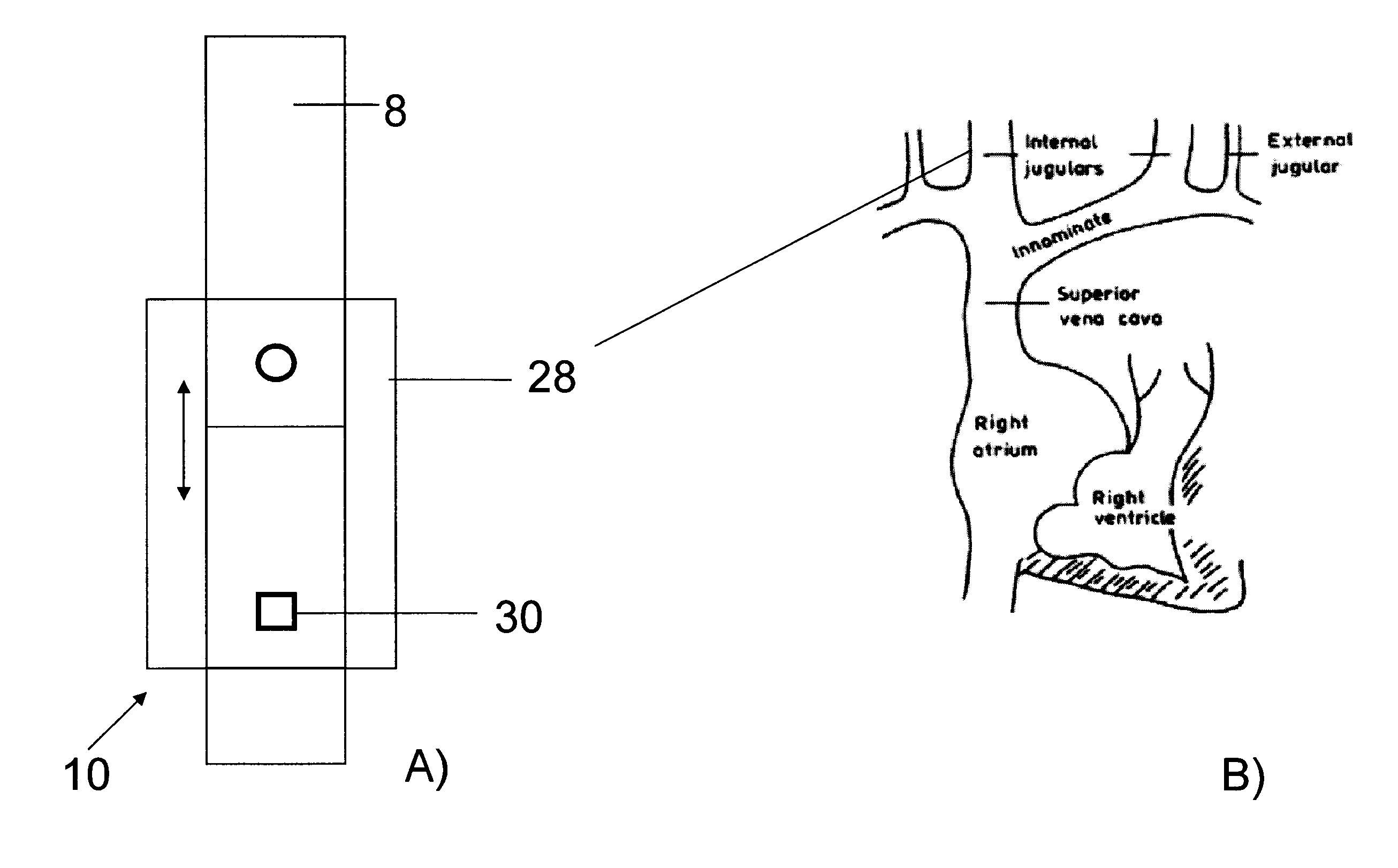
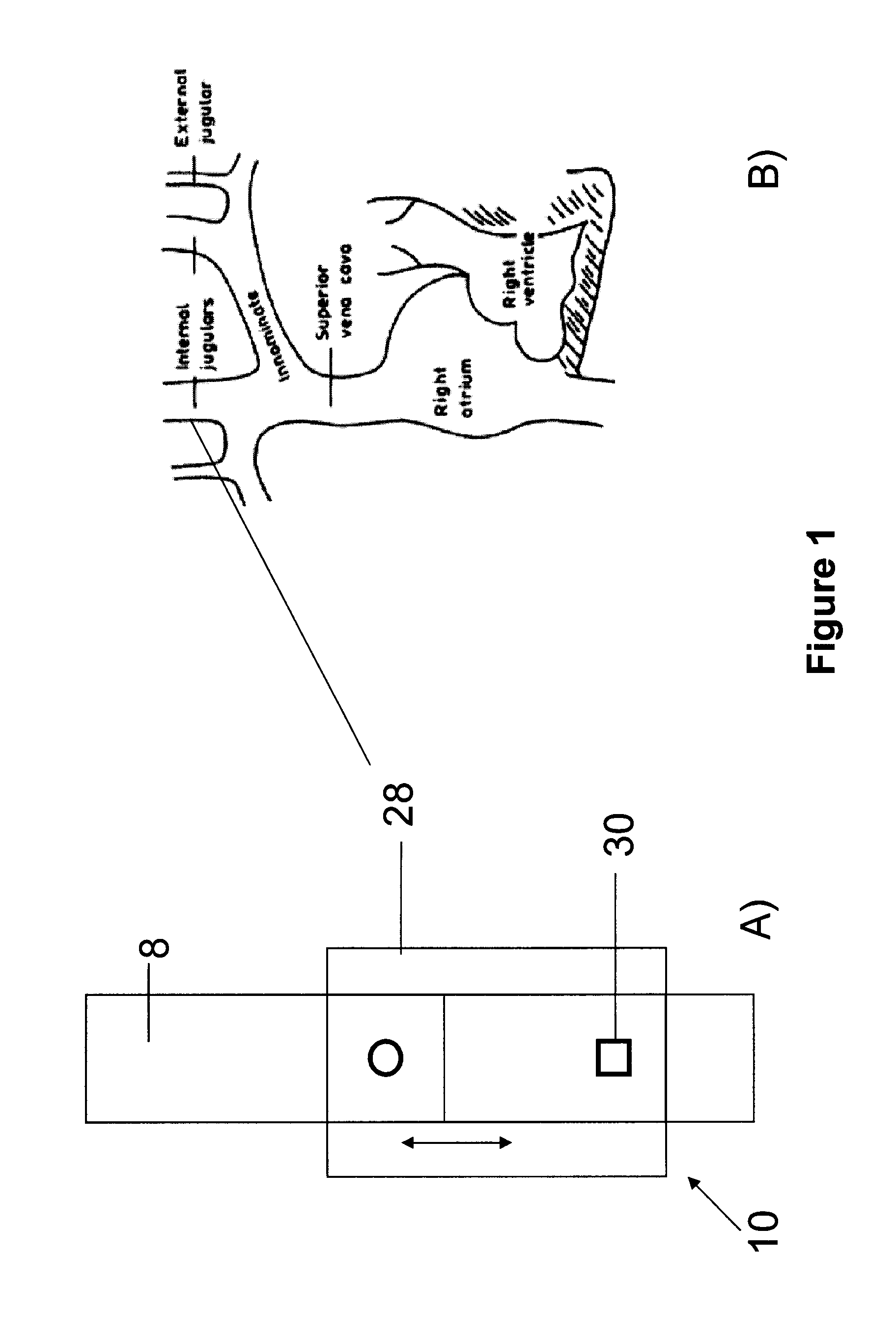
[0106]The venous pulse of a human subject was obtained using a device as shown in FIG. 1. The patient lay on a chair at about a 30 degree recline. The sensor patch of the device was placed on the neck of the patient at a site over the internal jugular vein. While the subject maintained normal breathing, venous pulse was measured and recorded. FIG. 12 illustrates the waveform recorded. The amplitude of the detected signal is represented along the y-axis while the x-axis represents time.

example 2

Measurement of Central Venous Pressure in a Patient

[0107]The central venous pressure of a human subject was obtained using a device as shown in FIG. 13. The sensor patch of the device was placed on the neck of the patient at a site over the internal jugular vein such that the terminal source / detector of the device was at the sternal angle of the subject. While the subject maintained normal breathing, venous pressure was measured and recorded as a function of body position when the patient was lying flat (0 degree incline, e.g. horizontal), at a partial rise (45 degree incline from the horizontal) and sitting upright (90 degree incline from the horizontal) as shown in FIG. 15A. The measured pressure as depicted by the waveform illustrated in FIG. 15B is consistent with the expected central venous pressure in a healthy subject which decreases as body position rises from the horizontal position.

example 3

Use of a Device with Pressure Sensor to Measure Patient CVP

[0108]A simulated patient system was developed to test a height sensor device 360 as shown in FIG. 18. The simulation (as shown in FIG. 19) included a cylindrical tissue phantom representing the patient's neck in which a tube 410 representing the jugular vein was embedded. A corresponding tube 412, joined at a T-junction to the jugular vein tube 410, represented a CVP catheter and was used to illustrate the height of fluid in the jugular vein. The fluid used in the system was water. A single tube extended downwardly from the T-junction and connected to a rubber “heart”. The heart is connected to a rotation pump which accurately simulates heart beats within the heart and pumps water through the system.

[0109]An optical sensor device with LED and photo detectors 328 (as in FIG. 13) was placed on the surface of the tissue phantom at a position that was over the simulated “jugular vein”. A pressure sensor 350 was placed on top of...


PUM


Abstract

A device for non-invasively measuring at least one parameter of a cardiac blood vessel in a patient comprises at least one light source that directs light at a tissue site on the patient; at least one photodetector adapted to receive light emitted by the light source and generate an output based on the received light, the output of said photodetector being correlated with a parameter of the blood vessel; and at least one probe for facilitating delivery of light from the light source to the tissue site, and receipt of light by the photodetector. The device may include a height sensor to adapt it for use to determine central venous pressure, or the configuration of light source(s) and photodetector(s) may be adapted to permit the device to provide attenuation correction in the determination of venous blood oxygenation.

Description

FIELD OF THE INVENTION[0001]The present invention is related to techniques for monitoring vital functions of the human body, including cardiac functions such as cardiac output and central venous blood oxygenation. It relates, in particular, to an optical method and device for the non-invasive and continuous monitoring of cardiac parameters such as blood flow, blood volume and blood oxygen saturation.BACKGROUND OF THE INVENTION[0002]The evaluation of jugular venous pulse has been an integral part of cardiovascular examination and has important clinical diagnostic values [1-2]. Jugular venous pulse is produced by the changes in blood flow and pressure in central veins caused by right atrial and ventricular filling and contraction. The two main objectives of the bedside examination of jugular vein pulse include the estimation of central venous pressure and the inspection of the waveform. Because of its more direct route to the right atrium, the right internal jugular vein is superior f...

Claims


Application Information

Patent Timeline
Patent Type & Authority Applications(United States)
IPC IPC(8): A61B5/1455A61B5/00A61B5/021A61B5/0295A61B5/024
CPCA61B5/14552A61B5/0295A61B5/6822A61B5/02433A61B5/02141A61B5/02427A61B5/0205A61B5/02116A61B5/0261A61B5/029A61B5/14551A61B2560/0261A61B2562/0233A61B2562/046
Inventor CHENG, XUEFENG
Owner MESPERE LIFESCI
Learn More