Type of testing equipment for detecting the failure process of thermal barrier coating in a simulted working environment

a testing equipment and working environment technology, applied in the direction of material flaw investigation, structural/machine measurement, instruments, etc., can solve the problems of thermal barrier coating failure and breakage, and high temperature alloy martial can no longer meet the urgent demand of advancing aero-engines, etc., to achieve strong applicability

Active Publication Date: 2015-12-10
XIANGTAN UNIV
View PDF4 Cites 64 Cited by
  • Summary
  • Abstract
  • Description
  • Claims
  • Application Information

AI Technical Summary

Benefits of technology

[0007]In order to resolve issues mentioned above, this invention offers a testing device that simulates working environment for thermal barrier coatings and detects real-time failure. This testing device manages to simulating high temperature, erosive, and corrosive condition for thermal barrier coating coated turbine blades at spinning state and actual working condition for guiding vanes at static state. This device integrates multiple non-destructive detection system that performs real-time detection of temperature field, strain field, surface topography, damage evolvement, interface topography on thermal barrier coating in various working environments so that better understanding of damaging mechanism of thermal barrier coating can be reached and reliable assessment and effective solution for improving design could be realized.Technological plans adopted by this invention are:

Problems solved by technology

Currently, nickel-base single crystal superalloys can withstand up to 1150° C., it's needless to say simply using high temperature alloy martial can no longer satisfy the urgent demand of advancing aero-engines.
During actual course of operation, thermal barrier coating could often fail or break due to crack, spall off, separation from interface.
There are many causes contributing to failure and breaking of thermal barrier coating.
Such strenuous working environment includes: (1) extensive time of high temperature.
Considering thermal barrier coating's complex geometric structure, sophisticated coupling effect of heat, force and chemistry, it is not practical to take the traditional approach of tensile, bending, heat fatigue, thermal stress to conduct research.
However, testing on actual aero-engines requires tremendous manpower and resources.
Nevertheless, with respect to simulating working environment, these devices could only simulate thermal fatigue of thermal barrier coatings, thermal shock or certain single loading working environment with a simple heat and force coupling effect, but not able to achieve simulating high temperature corrosive and erosive condition found in the working environment of thermal barrier coating.
Needless to say these devices failed to simulate working environment with a high-speed spinning condition for thermal barrier coating coated turbine blade.
With respect to real-time testing of the failure process, only Gong Shen-Kai and our earlier work managed to achieve acoustic emission testing, impedance spectroscopy spectrum testing of interface oxidation, but these non-destructive detection system did not form an integrated unit with the device.
These devices also did not have software performing simultaneous control of various non-destructive testing system and could not offer integrated display, record and analysis of various non-destructive testing data.

Method used


Image

  • Type of testing equipment for detecting the failure process of thermal barrier coating in a simulted working environment
  • Type of testing equipment for detecting the failure process of thermal barrier coating in a simulted working environment
  • Type of testing equipment for detecting the failure process of thermal barrier coating in a simulted working environment

Examples


Embodiment Construction

[0041]This invention offers a testing device capable of simulating the working environment of thermal barrier coating and performing real-time analysis of failure. Further details and illustrations are provided below on actual implementation of the device.

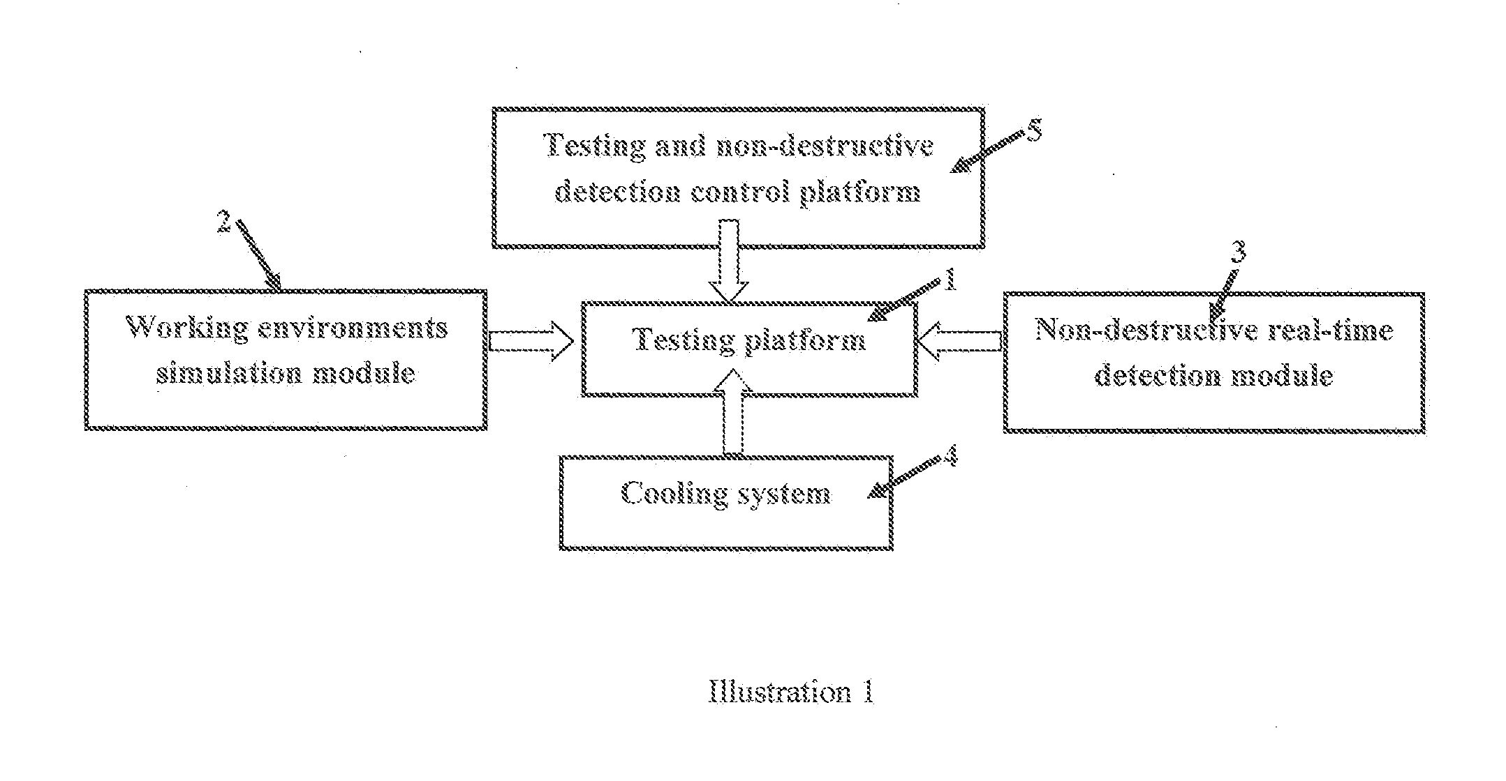
[0042]As shown in Illustration 1, structural components of this testing device includes: a testing platform, a working environment simulation module, a non-destructive detection module, a cooling system and a non-destructive detection control platform.

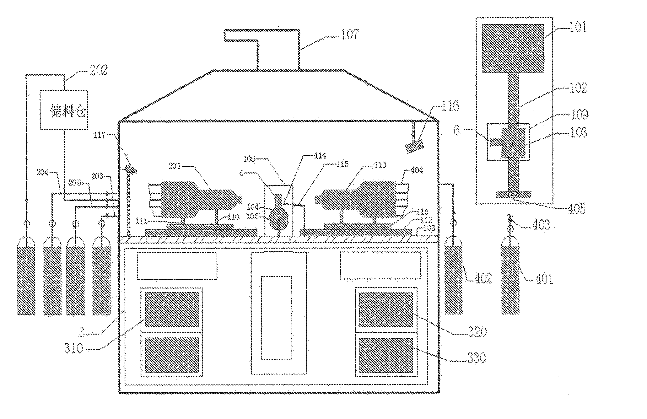
[0043]As shown in Illustration 2, Illustration 2 shows the structural components of this invention. The structure of the testing chamber consists of specimen holding apparatus (1) is installed in the middle of the testing platform, fastening device (105), a high-speed spinning motor (101), a spinning axle (102), a spinning state specimen holder (103); a static state specimen holder (104), installation axle (106) and static state specimen holder (104) engraved with scale marking, the h...


PUM

PropertyMeasurementUnit
temperatureaaaaaaaaaa
diameteraaaaaaaaaa

Abstract

A type of testing equipment for detecting the failure process of thermal barrier coating in a simulated working environment; it belongs to the field of simulated special working environment equipment. Testing equipment includes testing platform equipped with static or dynamic specimen holding apparatus, simulated module of working environment, real-time detection module, control panel. This invention is capable of simulating a high temperature, erosive, corrosive working environment for thermal barrier coated turbine blade of aero-engines; simulate high speed spinning working environment for thermal coated blade, simulate static working environment for guiding blade; perform real-time testing of temperature field, 3-D displacement field, crack initiation and expansion, surface oxidation, etc. This invention has achieved complete integration of high temperature, erosive, corrosive working environment for thermal barrier coating and complete integration static or dynamic working environment, complete integration of simulated working environment and real-time testing, thus providing a crucial testing platform and reference data to properly understand the failure mechanism of thermal barrier coated blade and to improve relevant designs; strong applicability.

Description

BACKGROUND OF THE INVENTION[0001]1. Field of the Invention[0002]This invention pertains to a testing device that detects real-time failure of thermal barrier coating in a simulated working environment. More specifically, this is about turbine blade of aero-engines in a simulated dynamic or static working environment with high temperature, corrosive, erosive conditions. This is a testing device that performs simultaneous testing of thermal barrier coating's failure under a particular working environment. This is a device that creates a special simulated working environment.[0003]2. Description of Related Art[0004]An aero-engine is regarded as the “heart” of an airplane, it bears crucial importance to the development of aviation industry. The key parameter of an aero-engine is its thrust-weight ratio. Taking the 1st generation F86 fighter and 4th generation F22 fighter as examples, thrust-weight ratio has grown from less than 2 to greater than 10. Obviously, raising aero-engine's thru...

Claims


Application Information

Patent Timeline
Patent Type & Authority Applications(United States)
IPC IPC(8): G01N17/00G01N17/04G01N3/56G01N25/72
CPCG01N17/002G01N3/56G01N17/04G01N25/72G01M15/02G01N3/567
Inventor ZHOU, YICHUNYANG, LIZHONG, ZHICHUNCAI, CANYING
Owner XIANGTAN UNIV
Why Eureka
Try Eureka