Supercharge Your Innovation With Domain-Expert AI Agents!

Microfluidic device

a microfluidic device and microfluidic technology, applied in the field of microfluidic devices, can solve the problems of increasing the complexity and cost of equipment involved, no commercially available products, and high mechanical strength of the device itself, and achieves the effects of reducing length and cross-section, enhancing mixing, and stable laminar flow

Active Publication Date: 2015-12-24
INDIAN INSTITUTE OF SCIENCE
View PDF0 Cites 5 Cited by
  • Summary
  • Abstract
  • Description
  • Claims
  • Application Information

AI Technical Summary

Benefits of technology

The present invention is a microfluidic device with a non-deformable section and a deformable section that can trigger instability in the laminar fluid flow, enhancing mixing of fluids as they flow through the device. This device can also improve mixing under turbulent conditions and at a faster pace. It has a reduced length and dimension, with a microconduit that disrupts stable laminar flow and causes a turbulent flow, resulting in improved mixing of fluids. The device has an inlet to allow in a stream of fluid with a desired flow rate and a stable laminar flow, and an outlet to collect the mixed fluid.

Problems solved by technology

Successful devices typically involve capillary action for fluid transport, and they do not incorporate fluid pumping or mixing within the device.
There are technological challenges to down-scaling processes that involve mixing, heating / cooling, pumping, reacting and metering of fluids, due to which there are no commercially available products that carry out these complex operations.
Due to the slow mixing, it is necessary for fluids to remain in contact for long periods of time.
Such large pressure drops require pumps and compressors to drive the flow, and increase the complexity and cost of equipment involved.
Such large pressure drops require a high mechanical strength of the device itself, since high pressures in systems of small dimensions could lead to mechanical failure.
The large path length also increases the volume of fluids and expensive reagents that are required.
There is also the difficulty of setting up fluid interconnects between the device and the surrounding fluid inputs or outputs which are strong enough to withstand the high pressures without leakage.
Therefore, one encounters the engineering limitation that the rates of mass and heat transfer are much lower than that in a turbulent flow.
This results in the requirement for long fluid paths in order to provide adequate residence time for mixing, and the consequent increase in the pressure requirements for pumping the fluid at low velocities.
Moreover, the large pressure differences often result in mechanical failure of the equipment due to the inability of the tubes and channels to withstand the large forces.
The requirement of external connections makes the device more complex and inflexible in its operation.
The important technological bottleneck to developing smaller and less complex networks is the slow mixing in these devices.
However, these strategies have the undermentioned limitations.
These require expensive fabrication techniques, where micron and sub-micron features have to be etched in silicon.
This increases the path-length of the flow and consequently the pressure drop and the power required.
This also increases cost due to complexity of fabricating tortuous channels or sub-micron structures.
The system also becomes more complicated and expensive due to the requirement of external electrical and magnetic circuits.
This increases the complexity and cost of fabrication significantly, and the pressure drop required to drive flow is also significantly higher.
This concept could be useful for pure fluids which do not contain suspended particles such as blood cells, but it is difficult to use for fluids with suspended particles, since the droplet size could be similar to the size of the suspended particles.
Complex channel shapes are usually required to enhance mixing and these increase the pressure drop, power requirement, and cost.
The inlet manifolds and the controls are also more complicated since two fluids have to be injected in specified sequence at pre-determined rates.
Droplets can be combined and separated and moved in pre-specified paths, but these require intricate controls which increase complexity and cost of the device.
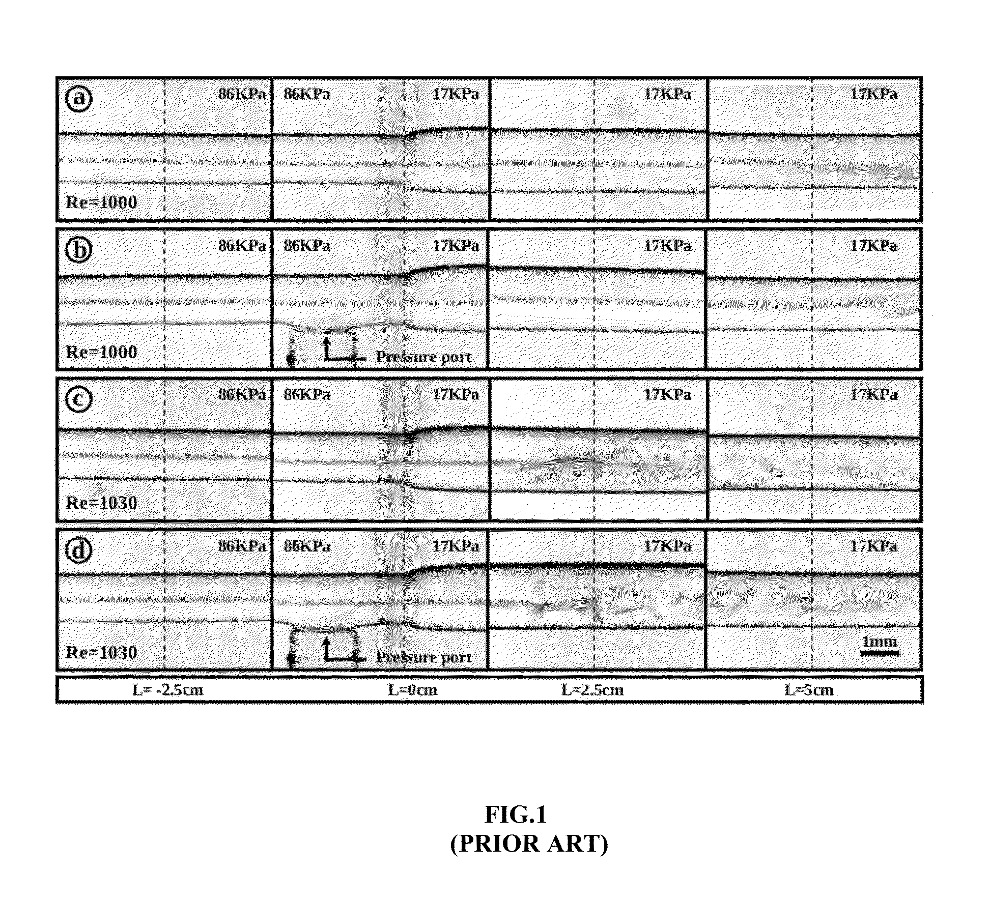
In the flow through flexible tubes, there theoretical studies have shown that there could be instability due to the interaction between the fluid and wall material.
It is also known that there could be instability even at Reynolds number less than 1, provided the fluid has very high viscosity (about 1000 times the viscosity of water) and the wall of the channel / tube is made sufficiently soft.
However, it is infeasible to use such low Reynolds number flows of very viscous fluids for microfluidic applications.
It was previously considered to be infeasible to use this mechanism for microfluidic applications where the Reynolds number with fluids having low viscosity from 1 to 10 times the viscosity of water at standard conditions, because the instability can be triggered at a Reynolds number less than the transition Reynolds number of 1000 in a channel only if the wall elasticity is less than 1 kPa, which is difficult to realize in practice.
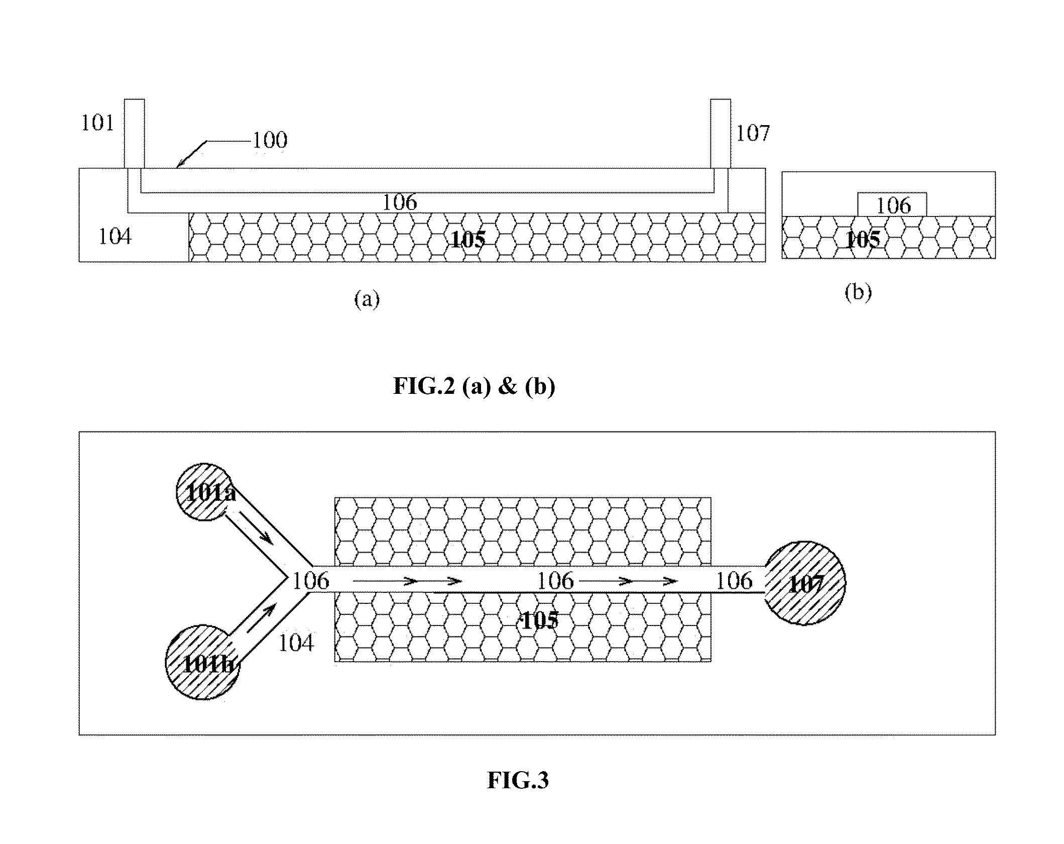
Though the objective of inducing a disruption of the laminar flow was achieved, the device was not found suitable for rapid mixing of fluids for many reasons such as the minimum dimension that could be achieved in the disclosed device was 0.8 mm, whereas for microfluidic applications, a minimum cross-section dimension of less than 500 μm, preferable 200 μm, is necessary.
Moreover, fabrication of microconduits of length 15-20 cm was also challenging task for use in microfluidic applications, since the dimensions of the known devices are in the order of 3-5 cm.
More significantly, the disclosed device does not disclose a complex network of microconduits that can be used in micro fluidic applications.
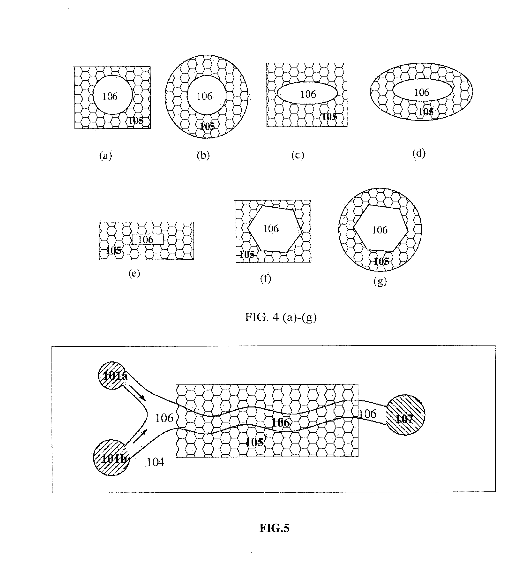
Consequently, mixing efficiency of the fluids in the device was poor.
Therefore, due to the combination of poor mixing and small cross-stream velocity fluctuations, it was considered infeasible to use the devices of this nature to generate rapid mixing in still smaller devices, since for microconduits of the length 3-5 cm and with the height of about 200 μm and 3-5 cm in length, the residence time of the fluid in the microconduit becomes smaller, by a factor of 4 to 6 in comparison to a tube of length 20 cm.
Due to this, the small magnitude of the velocity fluctuations results in poor mixing of fluids in such devices.
The requirement of external connections makes the device more complex and inflexible in its operation.
Even though these devices are commonly called lab-on-a-chip′ devices, they are actually ‘chip-in-a-lab’ devices which require large laboratory equipment to drive the flows.
The technological bottleneck to developing smaller and less complex networks is the slow mixing in these devices.

Method used


Image

  • Microfluidic device
  • Microfluidic device
  • Microfluidic device

Examples


Embodiment Construction

[0064]Accordingly, the present invention provides a microfluidic device with at least a micro-channel, having a non-deformable section and a deformable section, to trigger instability in the laminar fluid flow, while fluid is transiting through the micro-channel.

[0065]In an aspect of the present invention the structure of the microconduit of the microfluidic device is rendered soft enough, so that there is a flow instability, which involves wall oscillations of the microconduit, due to the coupling between the fluid flow and the motion of the walls of the microconduit. This instability occurs at a Reynolds number, which is lower than that for transition through a rigid microconduit of the same dimension, and it generates turbulent flow with significantly enhanced mixing of the selected fluids, in a substantially reduced period of time. For instance, considering the mixing time due to the diffusion of small molecules in a fluid such as water, in a device having a laminar flow of the ...


PUM


Abstract

A microfluidic device of the present invention is connected to at least an inlet to permit at least a stream of fluid with a desired fluid flow rate and a stable laminar flow. A body with at least a non-deformable portion and a deformable portion is connected to the inlet. At least a microconduit of substantially reduced length and cross-section, integrally formed in said non-deformable and deformable portions, and connected to the inlet. The stable laminar flow of fluid transiting through the microconduit is disrupted, resulting in a turbulent flow of the fluid, with a vibration of the deformable portion, when the fluid flow rate crosses a threshold value. The turbulent flow of the fluid undergoes an enhanced mixing, in a reduced period of time. At least an outlet is connected to microconduit to collect the mixed fluid. A network of microfluidic devices are arranged to perform mixing of fluids.

Description

TECHNICAL FIELD[0001]The present invention relates generally to microfluidic devices. More particularly, the present invention provides a microfluidic device having microfluidic conduit(s) to render enhanced mixing of fluid(s), in a reduced period of time, by inducing turbulence in laminar flow of the fluid(s).BACKGROUND OF THE INVENTION[0002]Microfluidic technologies have the potential to transform industries where high-value chemicals are processed in small quantities, such as health care, medical diagnostics, fine chemicals, etc. Some diagnostic devices, such as glucose meters and immunoassays are in use. Successful devices typically involve capillary action for fluid transport, and they do not incorporate fluid pumping or mixing within the device.[0003]There are technological challenges to down-scaling processes that involve mixing, heating / cooling, pumping, reacting and metering of fluids, due to which there are no commercially available products that carry out these complex op...

Claims


Application Information

Patent Timeline
Patent Type & Authority Applications(United States)
IPC IPC(8): B01L3/00
CPCB01L3/5027B01L2300/12B01L3/561B01L3/502761B01L3/502776B01L2200/0652B01L2300/0838B01L2300/0867B01L2300/0887B01L2300/123B01L2400/0655B01L2400/084B01L3/502746B01F31/312B01F33/30
Inventor KUMARAN, V.VERMA, MOHAN K. S.
Owner INDIAN INSTITUTE OF SCIENCE
Features
  • R&D
  • Intellectual Property
  • Life Sciences
  • Materials
  • Tech Scout
  • Unparalleled Data Quality
  • Higher Quality Content
  • 60% Fewer Hallucinations
Learn More