Wireless power system for portable devices under rotational misalignment

a technology of rotating misalignment and power circuitry, which is applied in the direction of transformers, inductances, safety/protection circuits, etc., can solve the problems of false alarms in the sensors and/or in the operation of wireless power circuitry, the wireless power circuitry reduces the space available for the sensors, and the incorrect operation

Inactive Publication Date: 2015-12-24
WIPQTUS
View PDF5 Cites 101 Cited by
  • Summary
  • Abstract
  • Description
  • Claims
  • Application Information

AI Technical Summary

Benefits of technology

[0021]To avoid a heated metal object safety issue caused by induced eddy currents when metal objects are placed in the magnetic flux coupling zone of the wireless power transmitter while the wireless power system is delivering power to the downstream load, the wireless power transmitter disclosed herein implements a metal object detect algorithm that is sensitive to wireless power receiver positional changes and wireless power system downstream load changes to effectively enable the wireless power system to detect such misplaced metal objects.
[0022]In an embodiment of the wireless power receiver, to protect the wireless power receiver circuitry from induced voltage spikes in excess of defined thresholds, the wireless power receiver disclosed herein includes a simple protection circuitry that naturally turns on and siphons out the excess power when the defined threshold is exceeded.

Problems solved by technology

When included in this valuable space, the wireless power circuitry reduces the space that is available for the sensors.
Their proximity may trigger incorrect operation and false alarms in the sensors and / or in the operation of the wireless power circuitry.
When the flat surface area is limited, the wireless power transmit circuitry in the charger and the wireless power receiver circuitry in the portable device are usually rotationally misaligned when the portable device is placed on the charger.
Even when there is sufficient flat surface area, the device may be placed on the charger in a fashion wherein there is significant rotational misalignment between the wireless power circuitries in the portable device and the charger.
When the level of rotational misalignment exceeds this level, the charger is unable to wirelessly charge the portable device.

Method used


Image

  • Wireless power system for portable devices under rotational misalignment
  • Wireless power system for portable devices under rotational misalignment
  • Wireless power system for portable devices under rotational misalignment

Examples


second embodiment

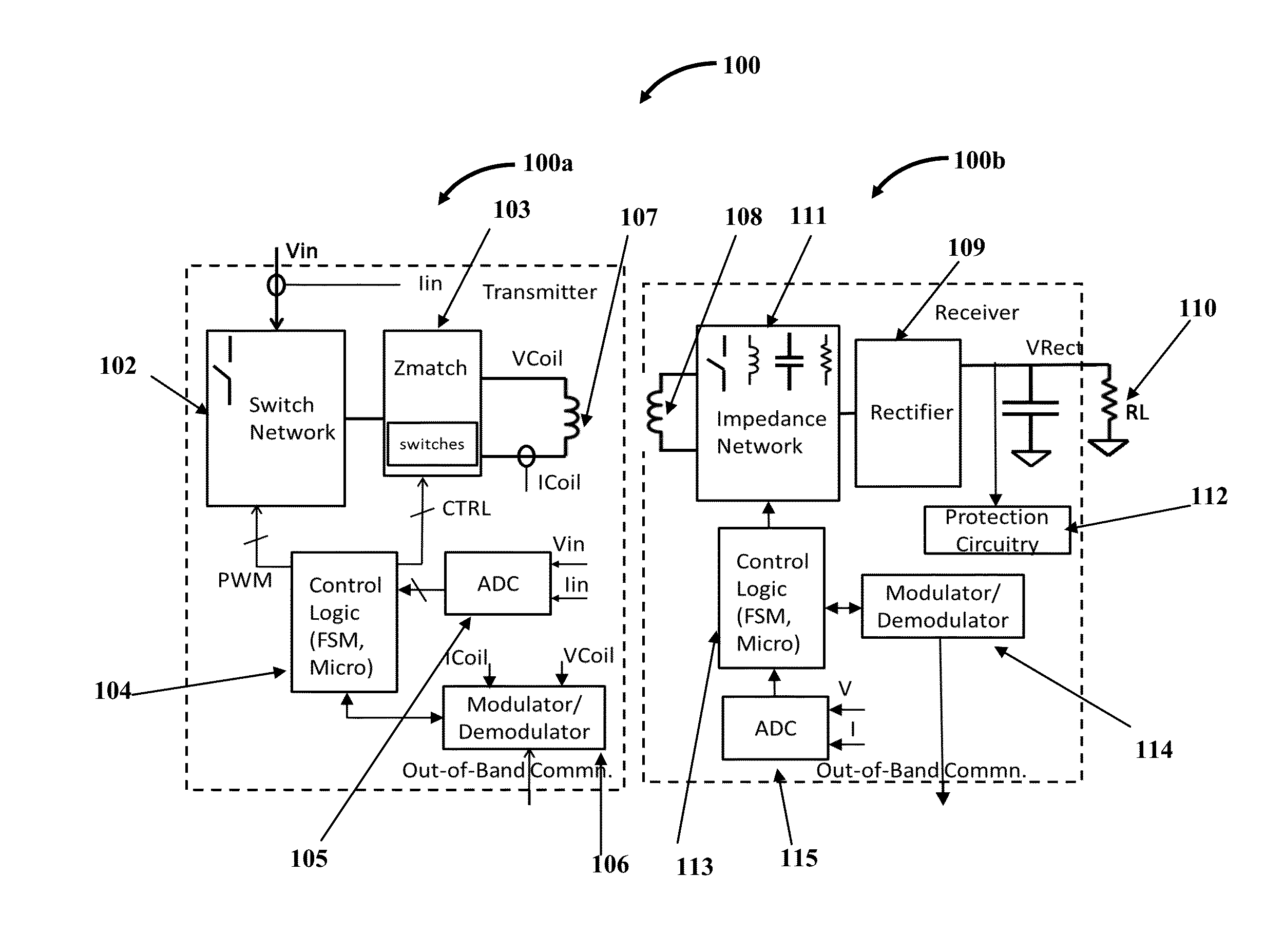
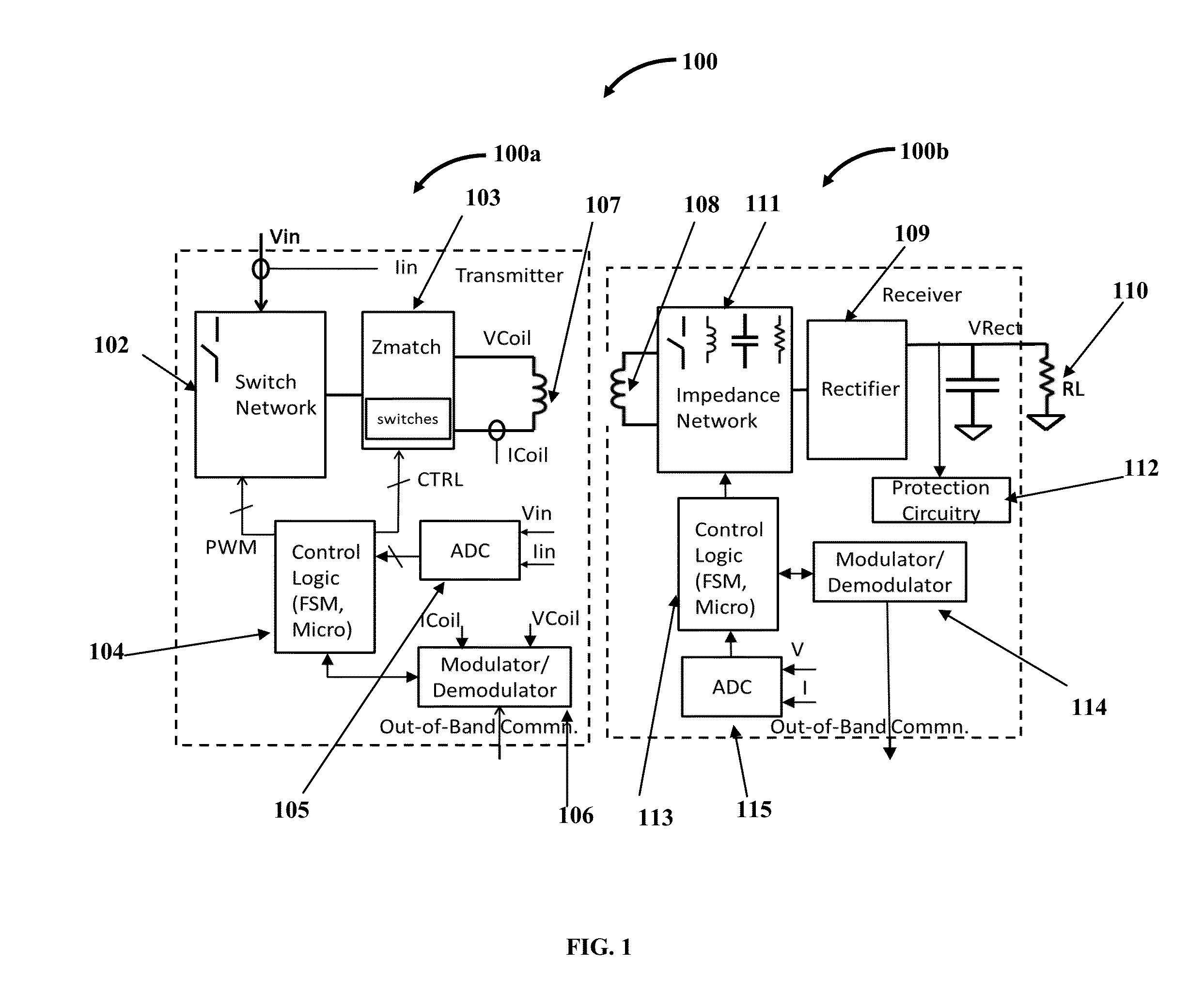
[0036]The wireless power transmitter 100a disclosed herein comprises a first circuit, a second circuit, a third circuit and a transmitter coil. The first circuit includes a switch network 102 as exemplarily illustrated in FIG. 1. The first circuit receives an input voltage Vin and current Iin from an external power source. In an embodiment, the first circuit includes a DC-DC power conversion block that is connected between the external power source and the switch network 102. The power conversion block is configured in one of multiple topologies such as buck, boost, buck-boost, etc., wherein the power conversion block, based on signals supplied to the first circuit from the third circuit, modifies the input DC voltage to higher value (step-up) or lower value (step-down) or leaves it unchanged (pass-through). In a second embodiment, the power conversion block may be configured as an AC-DC power supply where the external power supply is the AC mains and the power conversion block tran...

first embodiment

[0042]In the wireless power receiver, the control logic 113 combines the information received from the ADC block 115 with dynamic operational characteristics such as the frequency and duty cycle of wireless power that it measures via its specialized logic to sense the level of magnetic flux coupling between the coils of the wireless power transmitter 100a and wireless power receiver 100b. Based on the level of magnetic flux coupling and the power drawn by the downstream load (RL) 110, the control logic 113 communicates messages via the modulator / demodulator block 114 to the wireless power transmitter 100a to stop, maintain, increase or decrease the amount of wireless power transmitted. The control logic circuit 113 may additionally update the impedance of the impedance network 111, the topology of the rectifier 109 and the inclusion and configuration of the switched-capacitor / charge-pump / boost circuit of the rectifier 109 to further compensate for the level of magnetic flux coupling...


PUM


Abstract

A wireless power transmitter (WPT) including a first, second, third circuit and a transmit coil for wirelessly delivering power to a wireless power receiver (WPR) including a receiver coil, rectifier, impedance network, protection circuitry, control logic, modulator/demodulator and ADC is provided. A method that enables WPT and WPR to deliver the required power to the WPR's downstream load in planar, orthogonal and intermediate modes of WPR placement on WPT is provided. The WPR is integrated into the strap/frame or in the vital area of the device. To avoid a heated metal object safety issue, the WPT implements a metal object detect algorithm to detect metal objects and terminate transmission of power. To protect their circuitry from induced voltage spikes in excess of acceptable levels, the WPR includes a simple protection circuitry that naturally turns on and siphons out the excess power when the acceptable threshold levels are exceeded.

Description

BACKGROUND[0001]Wearable devices such as smart watches, fitness trackers, smart glass etc., are gaining in popularity in the marketplace today. Consumers who want to lose weight and / or improve their health can benefit from these wearable devices by being aware of the level of their physical activity on a day-by-day, week-by week basis, etc. Such awareness helps motivate the customer to use the stairs or walk the dog an extra lap around the block. These Wearable devices are smart and accurate. Besides measuring how much one walks, they provide good insight into lifestyle habits such as sleep, calorie consumption, heart rate, blood pressure, skin temperature, perspiration, etc.[0002]Wearable devices operate of a rechargeable battery. These batteries are typically recharged via a Universal Serial Bus (USB) Interface connectors or via wireless power. Wireless power enables a slimmer construction and waterproof capability for the Wearable device besides being a more convenient means for ...

Claims


Application Information

Patent Timeline
Patent Type & Authority Applications(United States)
IPC IPC(8): H02J5/00
CPCH02J7/025H02J50/10H02J5/005H02J50/60H02J50/90H02J7/00308H02J50/80
Inventor SANKAR, GANAPATHY
Owner WIPQTUS
Why Eureka
Try Eureka