
Electrochemical Machining Process

a technology of electrochemical machining and bil, which is applied in the direction of manufacturing tools, electrical-based machining electrodes, electric circuits, etc., can solve the problems of o and osub>, excessive gas bubble formation, and undesirable high hydrolysis rate of electrolyte, and achieve fast machining rate, prevent adverse machining effects, and constant removal of bil

Inactive Publication Date: 2016-01-07
HARVEST PRECISION COMPONENTS
View PDF5 Cites 0 Cited by
  • Summary
  • Abstract
  • Description
  • Claims
  • Application Information

AI Technical Summary

Benefits of technology

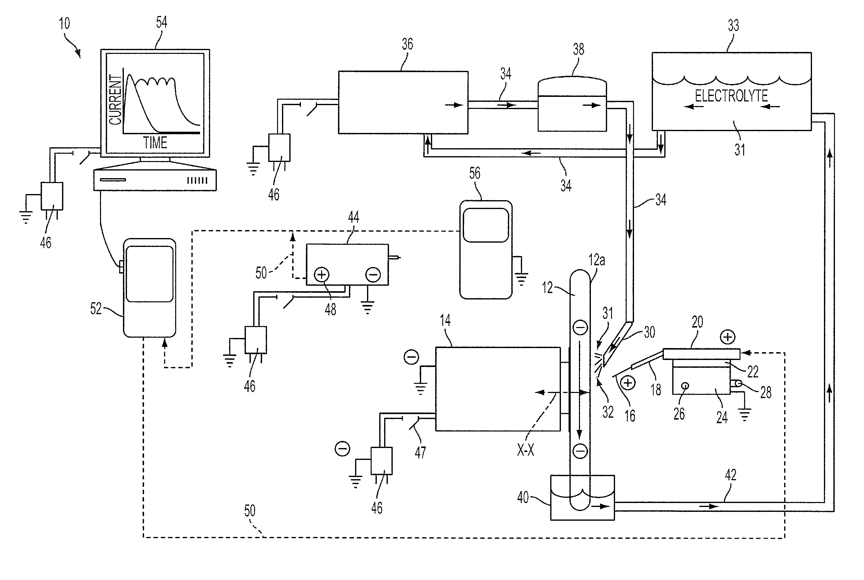
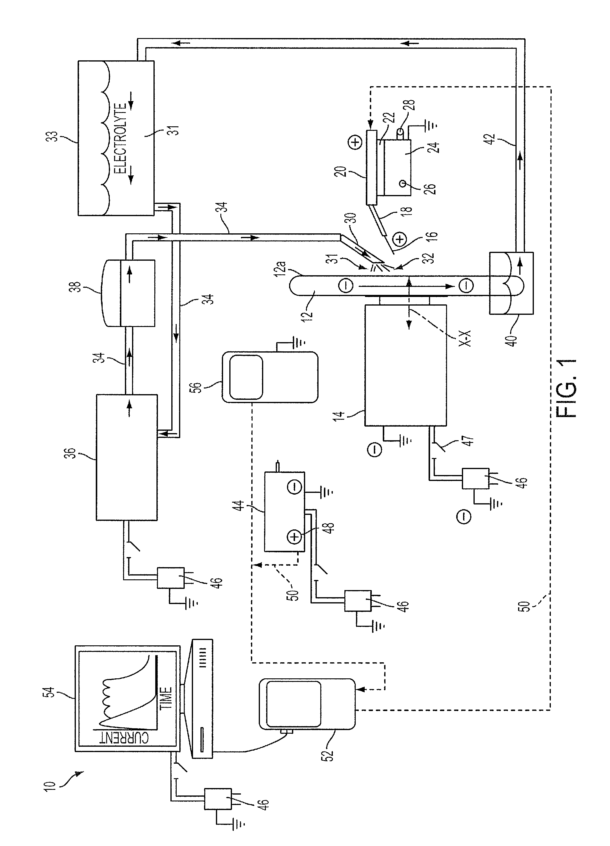
The invention relates to a new method for electrochemical machining (ECM) that uses a Beta insulating Layer (BIL) in the IEG. The BIL is constantly and uniformly removed through direct perturbing with a tool, resulting in a fast machining rate with a smooth surface. The tool constantly pulls and pushes the electrolyte into and out of the IEG, preventing the adverse machining effects caused by uncontrolled build-up of dissolution by-products. Overall, the invention provides a more efficient and effective method for ECM.

Problems solved by technology

In ECM, improvement in the machining rate of the work piece is desirable, however, the prior art has generally associated higher currents with higher machining rates, but have failed to understand or recognize that high currents also generate an undesirable high rate of hydrolysis of the electrolyte.
High rates of hydrolysis leads to the formation of an excessive amount of gas bubbles comprising O and O2 molecules emanating from the anodic work piece and H and H2 emanating from the cathodic tool.
Also, if the BIL is not being continuously removed from the work piece during machining, the BIL accumulates in the IEG and gas bubbles ultimately push through the accumulated BIL which creates momentary voids in the BIL which, in turn, allow a momentary and uncontrolled clear current path to the work piece.
Since the voids may appear anywhere in the BIL immediately adjacent to the work piece surface, this phenomenon creates pitting in the work piece surface as well as poorly defined edges at the peripheral boundaries of the point of machining.
This phenomenon of surface pitting and poor surface edges occurring due to gas bubbles pushing through an accumulated BIL has not been previously recognized by the prior art and hence has not heretofore been adequately addressed.

Method used


Image

  • Electrochemical Machining Process
  • Electrochemical Machining Process
  • Electrochemical Machining Process

Examples


example 1

[0053]A ceramic blade blank approximately (3 mm×7 mm×300 microns) was machined as described below using a work piece made of doped silicon carbide as described in commonly owned U.S. Pat. No. 6,616,890.

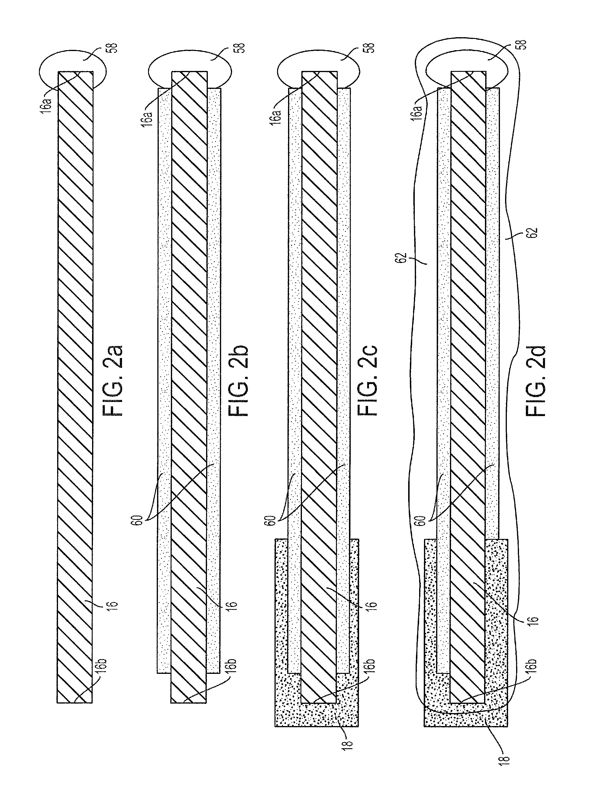
[0054]A first removable, electrically insulating coating comprising silicone material 58 was applied to the end 16a of the above-described blade blank 16 where machining was intended to occur. The blank 16 was then dipped into a Nickel plating bath to metalize the uncoated areas of the work piece to a plating thickness of 25-50μ. The plating was a continuous, lustrous coating of Ni 60. The plated work piece was then mounted in a brass holder 18 using an electrically conductive epoxy and then coated with a second removable, electrically insulating coating comprising wax 62 which covered the plating 60 as well as the first coating 58.

Preparing the Machine Set-Up

[0055]The brass holder 18 was then mounted into an electrically conductive steel holder of an X-Y mechanical, micrometer positi...


PUM

PropertyMeasurementUnit
constant distanceaaaaaaaaaa
linear resistanceaaaaaaaaaa
voltageaaaaaaaaaa

Abstract

Electrochemical machining method and apparatus wherein in one aspect of the invention, the machining voltage is selected to maintain the highest current without initiating substantial hydrolysis of the electrolyte flushed between the work piece anode and tool cathode. In another aspect of the invention, the Low Machining Potential Voltage (LPMV) and High Machining Potential Voltage (HMPV) for a particular work piece material are identified and the work piece is machined using a voltage at or between the LMPV and HMPV. In yet another aspect of the invention, direct perturbation of the Beta Insulating Layer (BIL) is carried out in an optimally small (between about near zero to about 10μ) inter-electrode gap (IEG) with constant and simultaneous pulling in and pushing out of the electrolyte through the IEG.

Description

BACKGROUND OF THE INVENTION[0001]The present invention relates generally to electrochemical machining (sometimes referred to as “ECM” herein) of a work piece, and more particularly relates to a novel method and apparatus for electrochemical machining of a work piece which represents a significant improvement over the present state of the electrochemical machining art.[0002]Electrochemical machining of an electrically conductive work piece is well known and involves a conductive work piece to be machined (anode), a tool (cathode) which is positioned in non-contact, spaced relation to the work piece, and an electrolyte comprising an electrically conductive fluid such as NaCI in H20, for example, flushed between the tool and work piece. The distance or spacing between the anode and cathode is termed the inter-electrode gap or “IEG”. A voltage is applied between the work piece and the cathode whereupon an electric circuit is established between the work piece and the cathode through the...

Claims


Application Information

Patent Timeline
Patent Type & Authority Applications(United States)
IPC IPC(8): B23H3/08B23H3/00B23H3/04
CPCB23H3/08B23H3/04B23H3/00B23H7/12B23H9/08B23H2400/10
Inventor MCPHILLIPS, RICHARD, B.
Owner HARVEST PRECISION COMPONENTS
Learn More