Eureka AIR delivers breakthrough ideas for toughest innovation challenges, trusted by R&D personnel around the world.

Use of fluorescent polymers in marking compositions for the diagnostic determination of cleaning performance

a technology of fluorescent polymers and compositions, applied in the direction of fluorescence/phosphorescence, rigid containers, disinfection, etc., can solve the problems of compromising the use of fluorescent marking systems to audit cleaning efficiency, unable to control with present antibiotics, and no patient is immune from the risk of infection

Active Publication Date: 2016-01-07
ECOLAB USA INC
View PDF3 Cites 21 Cited by
  • Summary
  • Abstract
  • Description
  • Claims
  • Application Information

AI Technical Summary

Benefits of technology

The patent describes a fluorescent marking composition that can be used to determine if a location has been cleaned. The composition includes a water-dispersible fluorescent polymer, a solvent, and a thickener. The polymer has a unique light absorption and emission spectrum. The method involves applying the composition to a surface and observing if any traces of the polymer remain after cleaning. The patent also describes a kit for use in applying the composition to surfaces, which includes the marking composition, a dispenser, an applicator, and optionally a UV light source. Overall, the patent provides a way to easily and efficiently determine if a location has been properly cleaned.

Problems solved by technology

Although certain individuals, such as the critically ill, the elderly, young children, and those with compromised immune systems are at greater risk, no patient is immune from the risk of acquiring an infection during a doctor visit or hospital stay.
For each of these pathogens, control with present antibiotics is problematic, if not impossible.
Use of fluorescent marking systems to audit cleaning efficiency is compromised, however, when the fluorescent mark is not thoroughly removed in the cleaning process.
It has been found that current products which use small molecule optical brighteners as fluorophores leave a “ghost” mark under ultraviolet light that cannot be further scrubbed off the surface.
Typical optical brighteners have high affinity for surfaces, which becomes problematic on older surfaces, highly porous surfaces, and surfaces cleaned with oxidizing agents (e.g. bleach, peroxide).
The presence of pores, scratches, nicks, pitting, and etching in the environmental surface makes it more difficult to completely remove the optical brightener from the surface.

Method used


Image

  • Use of fluorescent polymers in marking compositions for the diagnostic determination of cleaning performance
  • Use of fluorescent polymers in marking compositions for the diagnostic determination of cleaning performance
  • Use of fluorescent polymers in marking compositions for the diagnostic determination of cleaning performance

Examples


example 1

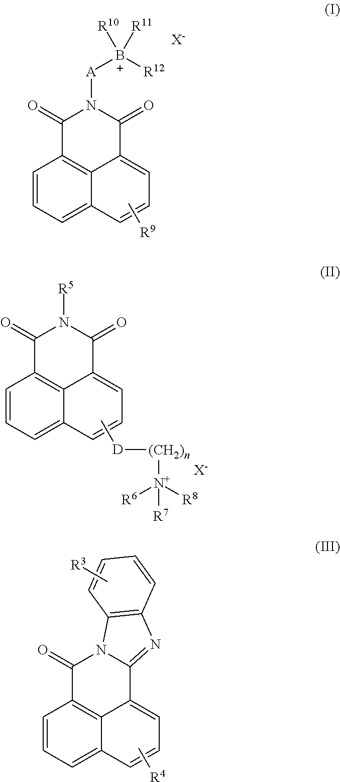
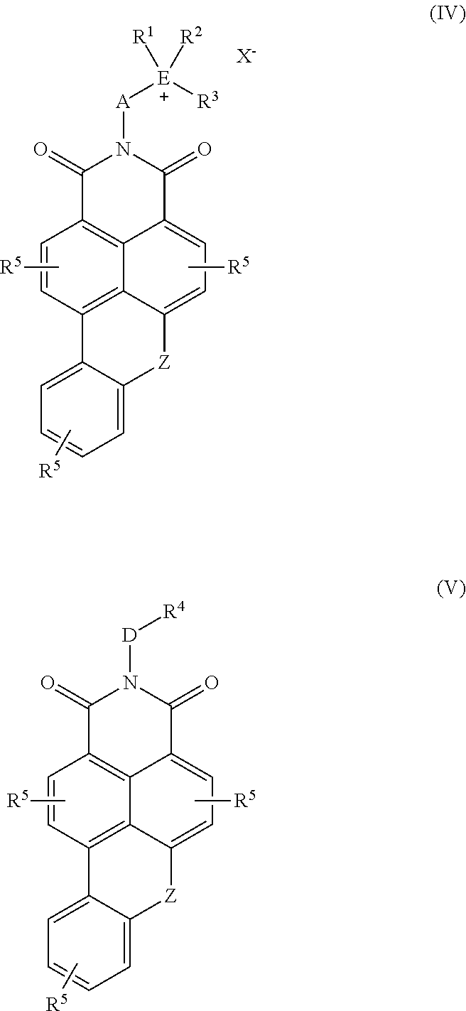
Synthesis of fluorescent monomer 4-methoxy-N-(3-N′,N′-dimethylaminopropyl)naphthalimide 2-hydroxy-3-allyloxypropyl quaternary salt (“BRT1”)

[0165]

Step One: Synthesis of 4-chloro-N-(3-N′,N′-dimethylaminopropyl)-naphthalimide (I)

[0166]A 500 mL 3-necked round bottom flask equipped with a mechanical stirrer (½ moon Teflon blade) and water condenser was charged with 4-chloro-1,8-naphthalic anhydride (23.3 g, 0.1 mol), 3-dimethylaminopropylamine (10.37 g, 0.102 mol), and glacial acetic acid (21 mL). The mixture was heated to reflux with stirring for three hours. Upon cooling, deionized water (200 mL) was added, followed by 50% sodium hydroxide solution (32 g, 0.3875 mol). The resulting tan precipitate was collected by filtration, washed with deionized water, and dried under vacuum.

Step Two: Synthesis of 4-methoxy-N-(3-N′,N′-dimethylaminopropyl)-naphthalimide (II)

[0167]A 250 mL 3-necked round bottom flask equipped with a mechanical stirrer (½ moon Teflon blade) and water condenser was charg...

example 2

Synthesis of fluorescent monomer 5-allyloxy-4′-carboxy-1,8-naphthoylene-1′,2′-benzimidazole

[0169]

Step One: Synthesis of 5-chloro-4′-carboxy-1,8-naphthoylene-1′,2′-benzimidazole (I)

[0170]A 100 mL round bottom flask was charged with 4-chloro-1,8-naphthalic anhydride (4.65 g, 19.99 mmol), 3,4-diaminobenzoic acid (3.08 g, 20.24 mmol), and glacial acetic acid (50 mL). The mixture was heated at reflux under nitrogen for five hours and then cooled. The solid was collected, washed with isopropanol, and dried under vacuum.

Step Two: Synthesis of 5-allyloxy-4′-carboxy-1,8-naphthoylene-1′,2′-benzimidazole

[0171]A 300 mL Parr reactor was charged with 5-chloro-4′-carboxy-1,8-naphthoylene-1′,2′-benzimidazole (I) (0.7 g, 2.01 mmol), allyl alcohol (20 mL, 0.294 mol), and potassium hydroxide (0.23 g, 4.1 mmol). The reactor was purged for 10 minutes, sealed, and then heated at 150° C. for four hours. Upon cooling, the volatiles were stripped and a crude orange solid was obtained.

example 3

Synthesis of fluorescent monomer 6-vinylbenzyloxy-4′-carboxy-1,8-naphthoylene-1′2′-benzimidazole

[0172]

Step One: Synthesis of 6-hydroxy-4′-carboxy-1,8-naphthoylene-1′,2′-benzimidazole (I)

[0173]A 100 mL round bottom flask was charged with 3-hydroxy-1,8-naphthalic anhydride (4.29 g, 20.04 mmol), 3,4-diaminobenzoic acid (3.04 g, 19.97 mmol), and glacial acetic acid (50 mL). The mixture was heated at reflux under nitrogen for five hours and then cooled. The solid was collected, washed with isopropanol, and dried under vacuum.

Step Two: Synthesis of 6-vinylbenzyloxy-4′-carboxy-1,8-naphthoylene-1′2′-benzimidazole

[0174]A 100 mL round bottom flask was charged with 6-hydroxy-4′-carboxy-1,8-naphthoylene-1′,2′-benzimidazole (I) (1.66 g, 4.5 mmol), vinyl benzyl chloride (0.92 g, 6.05 mmol), and potassium carbonate (2.38 g, 10 mmol). The mixture was heated at reflux in acetone for eight hours and then cooled. The mixture was then poured into water, acidified, and the orange solid was collected.


PUM

PropertyMeasurementUnit
weight average molecular weightaaaaaaaaaa
wt. %aaaaaaaaaa
wt. %aaaaaaaaaa

Abstract

The present invention generally relates to fluorescent marking compositions and their use to determine whether a surface has been cleaned. More particularly, the marking compositions comprise fluorescent polymers.

Description

FIELD OF THE INVENTION[0001]The present invention generally relates to fluorescent marking compositions and their use to determine whether a surface has been cleaned. More particularly, the marking compositions comprise fluorescent polymers.BACKGROUND OF THE INVENTION[0002]A nosocomial infection or hospital acquired infection (HAI) is an infection acquired in a healthcare facility by a patient admitted for some reason other than that specific infection. HAIs can be acquired in any setting in which healthcare is delivered, including acute care hospitals, ambulatory care settings, and long-term care facilities, such as nursing homes and skilled nursing facilities. Although certain individuals, such as the critically ill, the elderly, young children, and those with compromised immune systems are at greater risk, no patient is immune from the risk of acquiring an infection during a doctor visit or hospital stay.[0003]The pathogens causing significant nosocomial problems include MRSA (me...

Claims


Application Information

Patent Timeline
Patent Type & Authority Applications(United States)
IPC IPC(8): C09K11/02C09K11/06G01N21/64
CPCC09K11/025C09K2211/1466G01N21/6447C09K11/06C09B69/10G01N31/226C09K2211/1416C09K2211/1433C07D221/14C08G61/12G01N21/77G01N31/22A61L2/18A61L2/28C08F220/06
Inventor WEGNER, JOSEPHBROWN, ERINATKINS, JEFFERYZINN, PAULWALICKI, ROBERTHU, LANHUA
Owner ECOLAB USA INC
Why Eureka
Eureka Blog
Learn More