
A direct current circuit breaker and its implementation

a circuit breaker and direct current technology, applied in the direction of excess current switch operation, emergency protection arrangement for limiting excess voltage/current, and arrangement responsive to excess voltage, can solve the problems of oversize loss and poor economic nature, and achieve the effect of fast speed

Active Publication Date: 2016-01-07
STATE GRID COOP OF CHINA CO LTD
View PDF5 Cites 21 Cited by
  • Summary
  • Abstract
  • Description
  • Claims
  • Application Information

AI Technical Summary

Benefits of technology

The present invention provides the structure of a direct current circuit breaker. The breaker has a low on-state consumption because the converter circuit has fewer levels. The control method ensures the breaker runs safely, smoothly, and reliably.

Problems solved by technology

Generally speaking, there are two method to cut off the direct current, one is based on the general alternating mechanical switch, superimposing increasing oscillation current on direct current of the arcing gap by adding auxiliary circuit, cutting off the circuit by the current passes through zero, and the mechanical switch breaker is manufactured by this principle, it cannot meet the demands of the multi terminal flexible direct current transmission system on the breaking time; Another is that a high power cut-off power electronic device is used to break the direct current directly, although the solid-state breaker manufactured by this principle can meet the demands of the multi terminal flexible direct current transmission system on the breaking time, it has an oversize loss and poor economic nature when it is turned on normally.

Method used


Image

  • A direct current circuit breaker and its implementation
  • A direct current circuit breaker and its implementation
  • A direct current circuit breaker and its implementation

Examples


Embodiment Construction

[0052]The following examples are provided to illustrate the present invention, and should not be limitative of the scope of this novel device.

[0053]The detail of the embodiments is described as below incorporated with the figures by way of cross-reference.

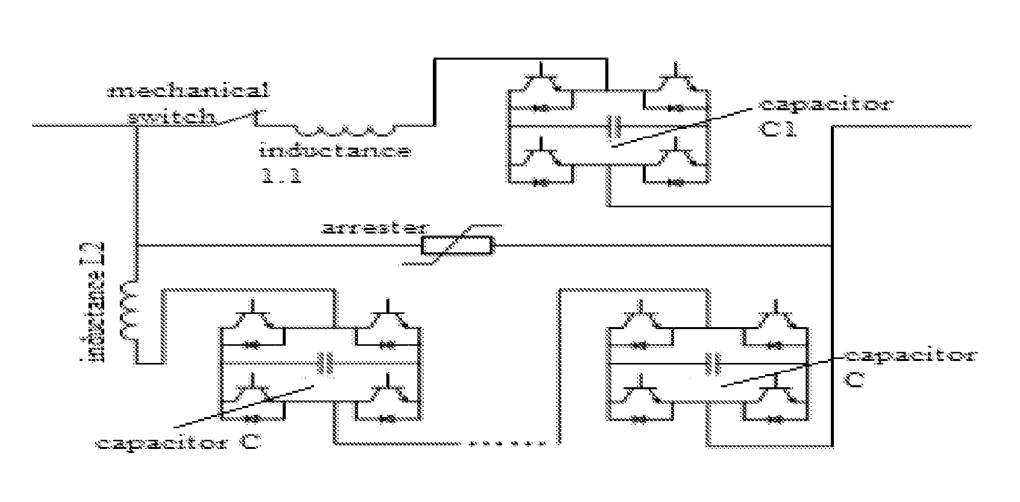
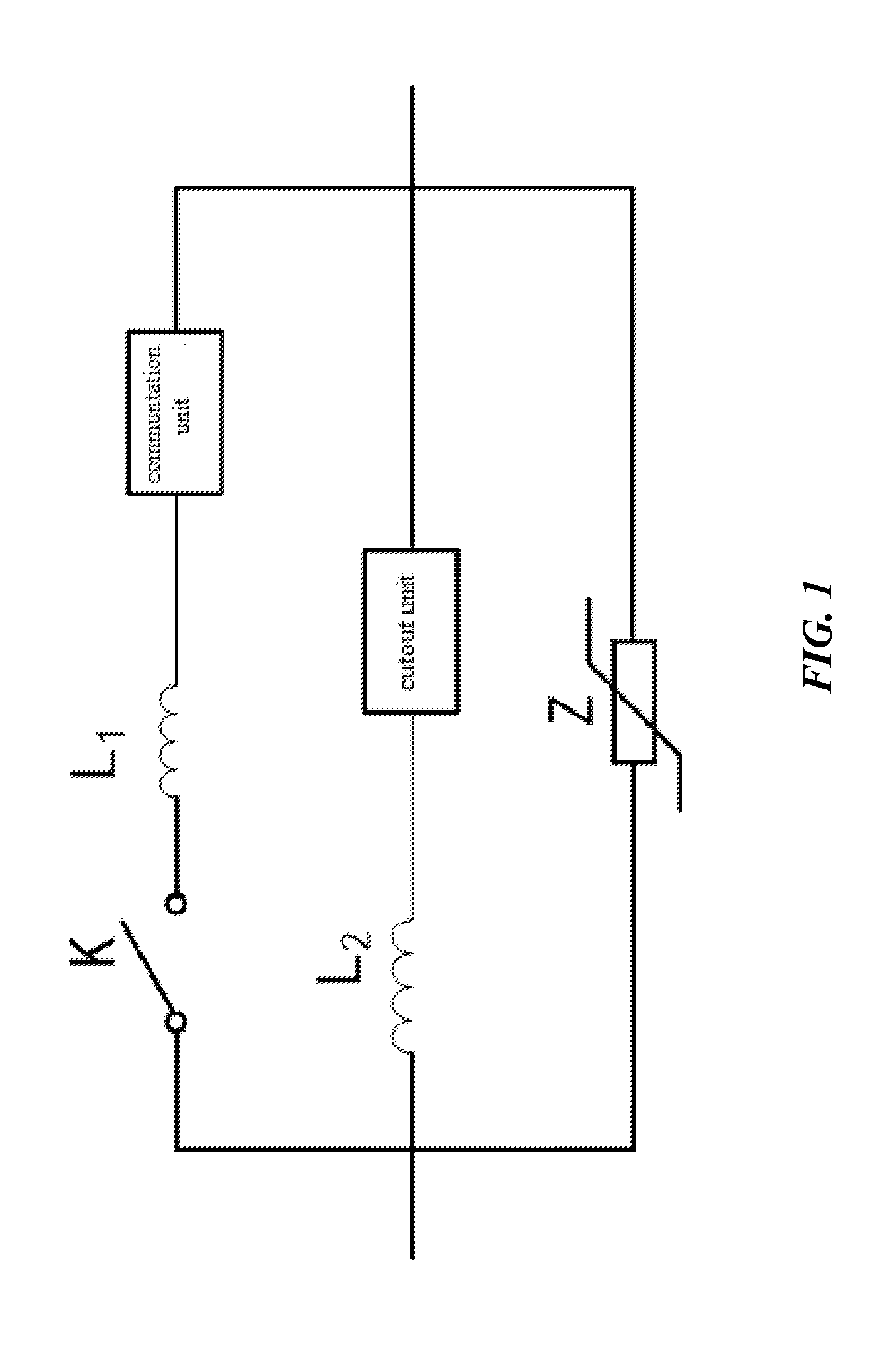
[0054]A breaker is illustrated by the present embodiment, its electrical structure shown as FIG. 1, including the cutout circuit, the commutation circuit and the energy absorption circuit connected in parallel.

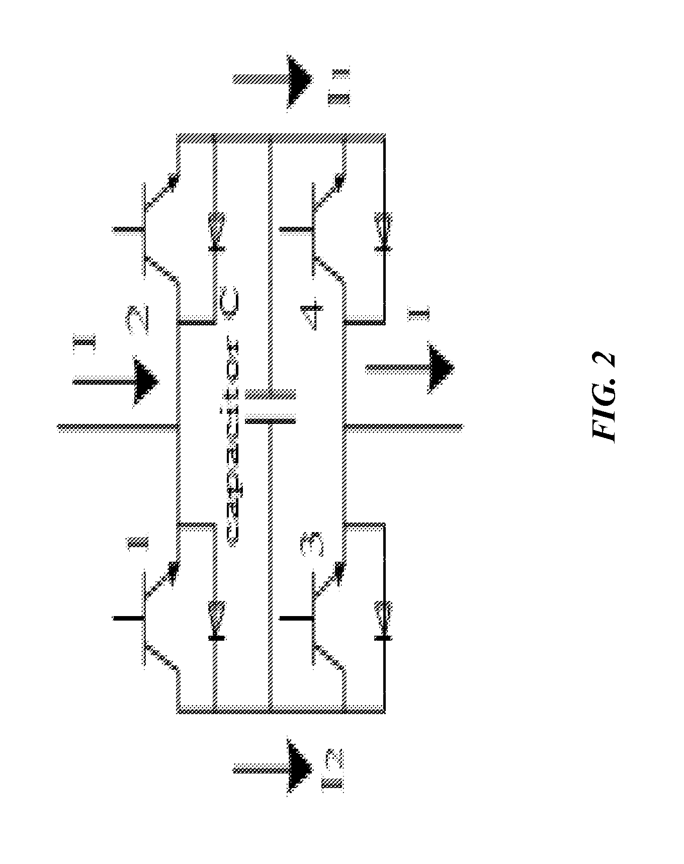
[0055]The commutation circuit is used for switching the external current into cutout circuit, including commutation inductance, commutation unit and mechanical switch connected in series, turn-on the bidirectional current; The commutation unit only enduring the on-state voltage drop when the cutout switch turns on; When the high speed switch cuts off, it endures the voltage of the whole breaker. Wherein, the number of the mechanical switch is at least one, so that it can endure the higher voltage.

[0056]The cutout circuit is i...


PUM


Abstract

The present invention provides a direct current circuit breaker and its implementation method, which includes the cutout circuit, the commutation circuit and the energy absorption circuit connected in parallel, wherein the cutout circuit includes cutout inductance and cutout unit connected in series, the commutation circuit includes commutation inductance, commutation unit and mechanical switch connected in series, commutation unit has a smaller on-resistance compared to cutout unit. The direct current circuit breaker topology of the present invention is novelty, concise, fully functional, easy to control and can flexible extend to apply to different voltage occasion. Through using power semiconductor switch module to cut off the current, It will have a quickly action, without generating electric arc, while the modular construction also reduces the consistency requirements of the power electronic component, and easy to realize the voltage-sharing of the power semiconductor in series, the capacitor included in the module also plays a role of limiting the current. Commutation circuit and cutout circuit through the full-bridge structure can realize the shunt, reduce the current stress of the power electronic component, and also reduce the component cost.

Description

FIELD OF THE INVENTION[0001]The invention relates to a power electronic technology, more particularly, to a direct current circuit breaker and its implementation process.BACKGROUND OF THE INVENTION[0002]As the technology based on the multi terminal flexible direct current of the VSC and DC power grid comes to be used, the quick direct current circuit breaker becomes the key device to ensure the system running security, stability and reliability. In the exchange system, the alternating current has two natural zero-crossing points in a period, the alternating current circuit breaker just uses the current natural zero-crossing point to cut off the current, meanwhile the direct current has no natural zero-crossing point, therefor, the cut off of the direct current is far more different than the cut off of the alternating current.[0003]Generally speaking, there are two method to cut off the direct current, one is based on the general alternating mechanical switch, superimposing increasin...

Claims


Application Information

Patent Timeline
IPC IPC(8): H02H3/38H02H9/02
CPCH02H9/02H02H3/38H01H33/596H02H7/268H02J1/00H01H9/542H01H83/20H02H3/08
Inventor TANG, GUANGFUGAO, CHONGLUO, XIANGWEI, XIAOGUANGQIU, YUFENGCAO, JUNZHENG
Owner STATE GRID COOP OF CHINA CO LTD
Learn More