Sensor for determining gas concentration

a technology of gas concentration and sensor, which is applied in the field of sensors and a method for determining gas concentration, can solve the problems of inability to reliably perform capnography, cumbersome or impossible for others, and often not reliable methods, so as to improve the accuracy of said radiation supply means, reduce thermal gradient, and improve heat distribution

Active Publication Date: 2016-01-14
KONINKLJIJKE PHILIPS NV
View PDF3 Cites 10 Cited by
  • Summary
  • Abstract
  • Description
  • Claims
  • Application Information

AI Technical Summary

Benefits of technology

[0042]Preferably, the second heat conducting means comprises at least one extension part at least partially extending into the sensing means. This is identical to the above-described situation. In particular, the at least one extension part may be column-shaped and may extend from the part of the second heat conducting means covering the gas-permeable layer, and may penetrate into the sensor means. Preferably, said extension part penetrates at least the gas-permeable layer, and preferably also at least partially the sensing layer. This allows a better heat distribution inside the sensor means, thereby leading to reduces thermal gradients.
[0043]Preferably, the optical sensor unit further comprises second thermal insulation means configured to thermally isolate the first heating device from the at least one radiation supplying means and / or the at least one radiation detection device. In particular, the second thermal insulation means may be interposed between the first heating device and the radiation supplying means and / or the at least one radiation detection device, in order to avoid heat from being introduced from the first heating device into the radiation supplying means and the radiation detection device. Accordingly, temperature effects on the radiation supplying means and / or the radiation detection device are avoided, thereby increasing accuracy of said radiation supplying means and radiation detection device.
[0044]Preferably, the optical sensor unit further comprises at least one second heating device configured to heat the at least one radiation supplying means and / or the at least one radiation detection device while being thermally isolated from the first heating device by the second thermal insulation means. The second heating device may be used to keep a stable temperature of the radiation supplying means and the detection device, so that a detection accuracy and sensitivity is maintained. Furthermore, the at least one second heating device may be used to perform an active zero heat flux (ZHF) method. Thus, the second heating device may be controlled to heat the radiation detection device and / or the radiation supplying means in order to actively reduce a temperature gradient between the sensor means and the radiation supplying means and / or the at least one radiation detection device, thereby minimizing heat flux into the sensor means. For instance, a temperature of the at least one second heating device (and preferably of the at least one radiation supplying means and / or the at least one radiation detection device) may be adjusted using the second heating device to be essentially equal to a temperature sensed for instance at the first heat conducting means or at the patient's skin. Thereby, a temperature gradient across the optical sensor unit, in particular across the sensor means, in a perpendicular direction is minimized.

Problems solved by technology

However, in case of non-invasive ventilation where air leaks between mask and face are usually present and the patients have severe respiratory diseases capnography is often not a reliable method.
Transcutaneous CO2 monitoring is not disrupted by air-leaks and respiratory diseases but requires trained personal to obtain reliable values and shows some inaccuracy due to variation in skin properties among adults.
This is well feasible in certain application fields of these sensor spots but is cumbersome or impossible for others.
When shifting from this (intended) application towards a transcutaneous sensor an additional problem arises, namely:
It is a new and highly relevant problem in chemo-optical sensor spots applied for transcutaneous sensing, as thermal gradients are inevitably present.

Method used


Image

  • Sensor for determining gas concentration
  • Sensor for determining gas concentration
  • Sensor for determining gas concentration

Examples


first embodiment

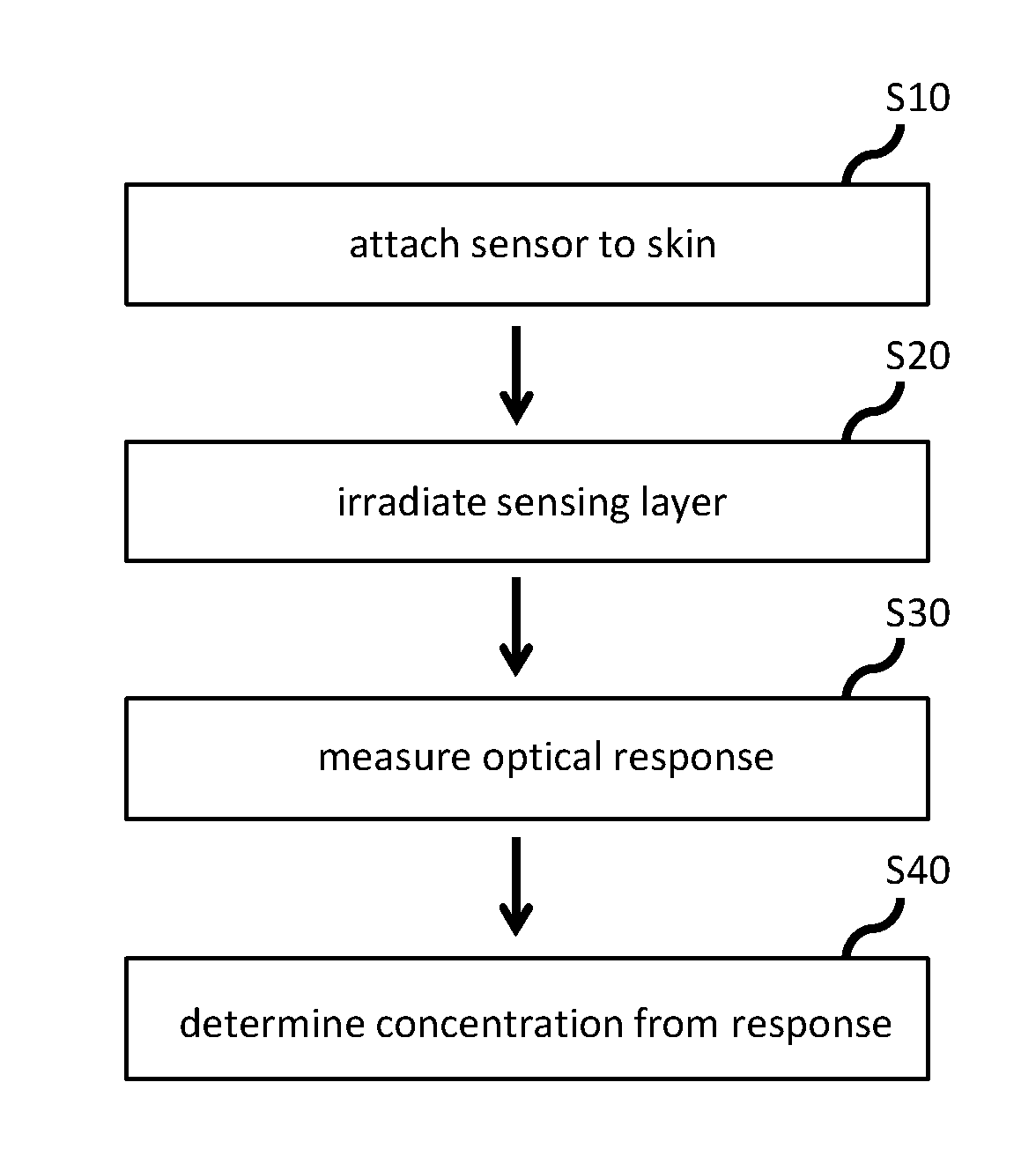
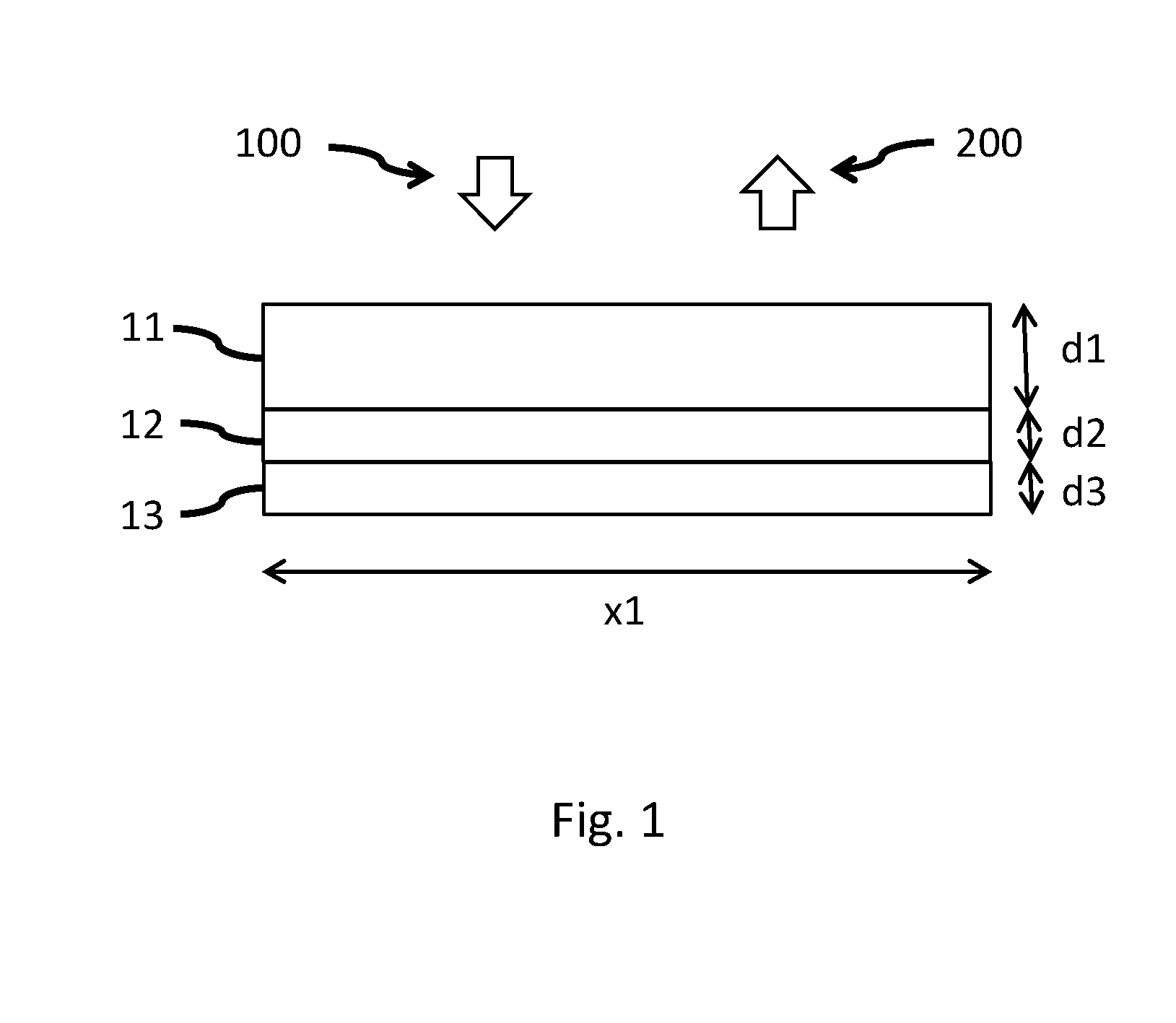
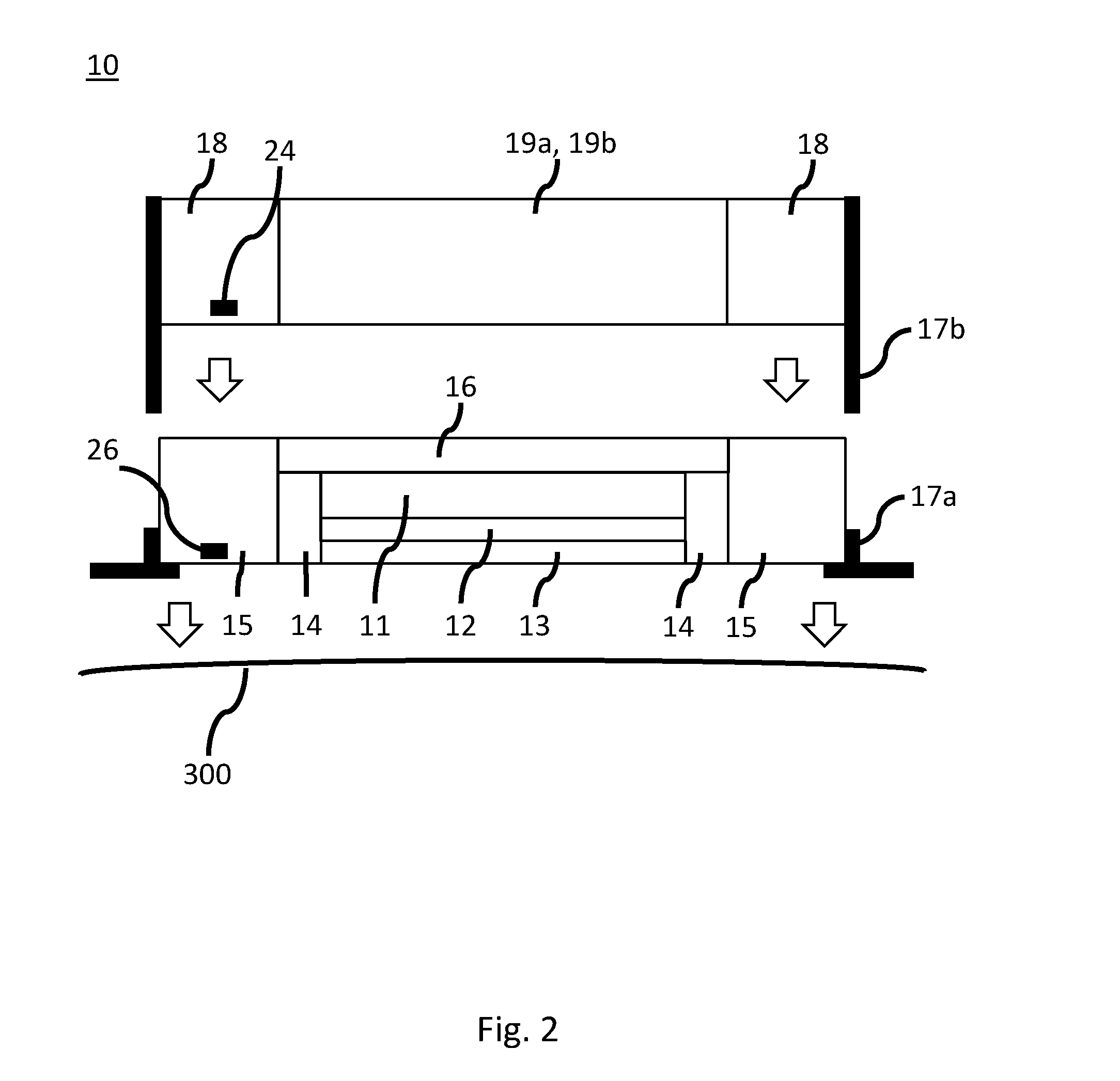
[0058]FIG. 2 shows a sectional view of an optical sensor unit 10 according to the present invention. The optical sensor unit 10 may have a circular shape and may be attached to skin 300 of a patient. The optical sensor unit 10 comprises sensor means (12, 13) comprising a gas-permeable layer 13 and a sensing layer 12 overlying the gas-permeable layer 13. The gas-permeable layer 13 may be in contact with the skin 300, wherein preferably a contact fluid is provided between the skin and the gas-permeable layer 13 in order to ensure proper gas diffusion. An optical transparent layer 11 covers the sensing layer 12. First thermal insulation means 14 at least partially surround lateral sides of the optically transparent layer 11, the sensing layer 12 and / or the gas-permeable layer 13, in order to thermally isolate said layers from its environment. An interface layer 16 is provided to cover at least the optically transparent layer 11, and serves as optical coupling. The interface layer 16 ha...

second embodiment

[0063]The optical sensor unit 10 further includes a portion 15a of the first heat conducting means 15 provided between the sensor means (12, 13), in particular the gas-permeable layer 13, and the skin 300. The portion 15a is perforated to allow gas exchange. In particular, the portion 15a may be a thin sheet of perforated metal. The metal may be the same metal the first conducting means 15 is made of. Accordingly, thermal gradients in the sensor means (12, 13) in a direction parallel to the gas-permeable layer / sensing layer are suppressed and a temperature of the sensor means is well-defined, thereby increasing accuracy of the gas concentration measurement.

[0064]FIG. 4 shows a sectional view of an optical sensing unit 10 according to a third embodiment of the present invention. The third embodiment differs from the first embodiment shown in FIG. 2 in the provision of second heat conducting means 20a, 20b. The second heat conducting means 20a, 20b comprises an extending portion 20a ...


PUM

PropertyMeasurementUnit
temperatureaaaaaaaaaa
thickness d3aaaaaaaaaa

Abstract

The present invention provides an optical sensor unit (10) for measuring gas concentration, comprising: sensor means (12, 13) and first thermal insulation means (14, 16) at least partially surrounding said sensor means (12, 13). The sensor means (12,13) includes at least one sensing layer (12) adapted to be irradiated with a predetermined radiation (100), and at least one gas-permeable layer (13) adjacent to one side of the at least one sensing layer (12) and adapted to pass gas, which concentration is to measured, through the gas-permeable layer (13) towards the at least one sensing layer (12). The optical sensor unit (10) is adapted to measure an optical response of the at least one sensing layer (12), which optical response depends on the gas concentration.

Description

TECHNICAL FIELD[0001]The present invention relates to a sensor and a method for determining gas concentration.BACKGROUND OF THE INVENTION[0002]Neuromuscular disease, chronic obstructive pulmonary disease (COPD) and obese hypoventilation patients often suffer from chronic respiratory failure. Said patients need regular treatment of their respiratory failure at home. Hypoxemic patients are treated by oxygen therapy (mostly without ventilator support), while treatment by Invasive Ventilation (IV) or Non Invasive Ventilation (NIV) with environmental air helps bringing the high carbon dioxide blood gas level of hypercapnic patients back to an acceptable level. The efficacy of the ventilation is checked by measuring the base-line and the trends in the arterial oxygen and carbon dioxide levels during nocturnal ventilation.[0003]Arterial blood gas measurements form the golden standard. Before starting ventilation treatment at home, patients stay at the hospital to optimize ventilator settin...

Claims


Application Information

Patent Timeline
Patent Type & Authority Applications(United States)
IPC IPC(8): A61B5/1455A61B5/00A61B5/1491G01N21/59G01N33/00
CPCA61B5/14552G01N33/004G01N2201/062A61B5/1491A61B5/6833G01N21/59
Inventor KAHLMAN, JOSEPHUS ARNOLDUS HENRICUS MARIAVAN KESTEREN, HANS WILLEMLAMBERT, NICOLAASJANSEN, THEODORUS PETRUS HENRICUS GERARDUS
Owner KONINKLJIJKE PHILIPS NV
Why Eureka
Try Eureka