Electroacoustic transduction film
a transducer and electroacoustic technology, applied in the direction of electric transducers, plane diaphragms, electrical apparatus, etc., can solve the problems of affecting the aesthetics of the flexible display, the loss of light weight and flexibility, and the inability to achieve the desired output properties, so as to prevent a decrease in properties and stably exhibit desired output properties
- Summary
- Abstract
- Description
- Claims
- Application Information
AI Technical Summary
Benefits of technology
Problems solved by technology
Method used
Image
Examples
example 1
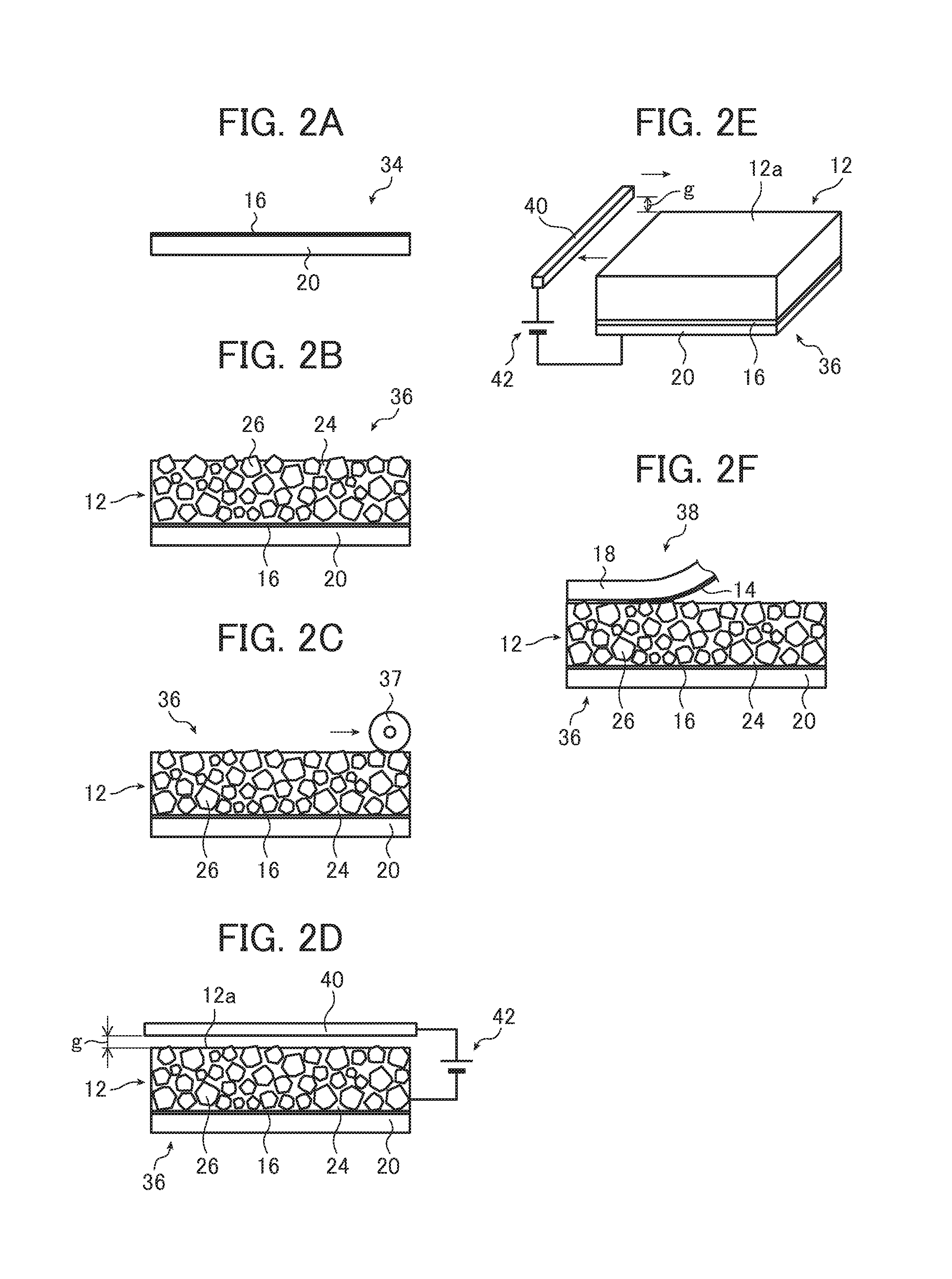
[0193]Cyanoethylated PVA (CR-V manufactured by Shin-Etsu Chemical Co., Ltd.) was dissolved in dimethyl formamide (DMF) at the following compositional ratio. After that, PZT particles were added to this solution as the piezoelectric body particles 26 at the following compositional ratio, and were dispersed by using a propeller mixer (the number of rotations of 2000 rpm), and thus a coating for forming the piezoelectric layer 12 was prepared.
PZT Particles300 parts by mass Cyanoethylated PVA30 parts by massDMF70 parts by mass
[0194]Furthermore, as the PZT particles, PZT particles in which a mixed powder formed by wet mixing a powder of a Pb oxide, a Zr oxide, and a Ti oxide as a main component using a ball mill such that Zr is 0.52 mol and Ti is 0.48 mol with respect to Pb of 1 mol was calcined at 800° C. for 5 hours, and then subjected to crushing processing.
[0195]On the other hand, the sheet-like materials 34 and 38 were prepared in which a copper thin film having a thickness of 0.1 μ...
example 2
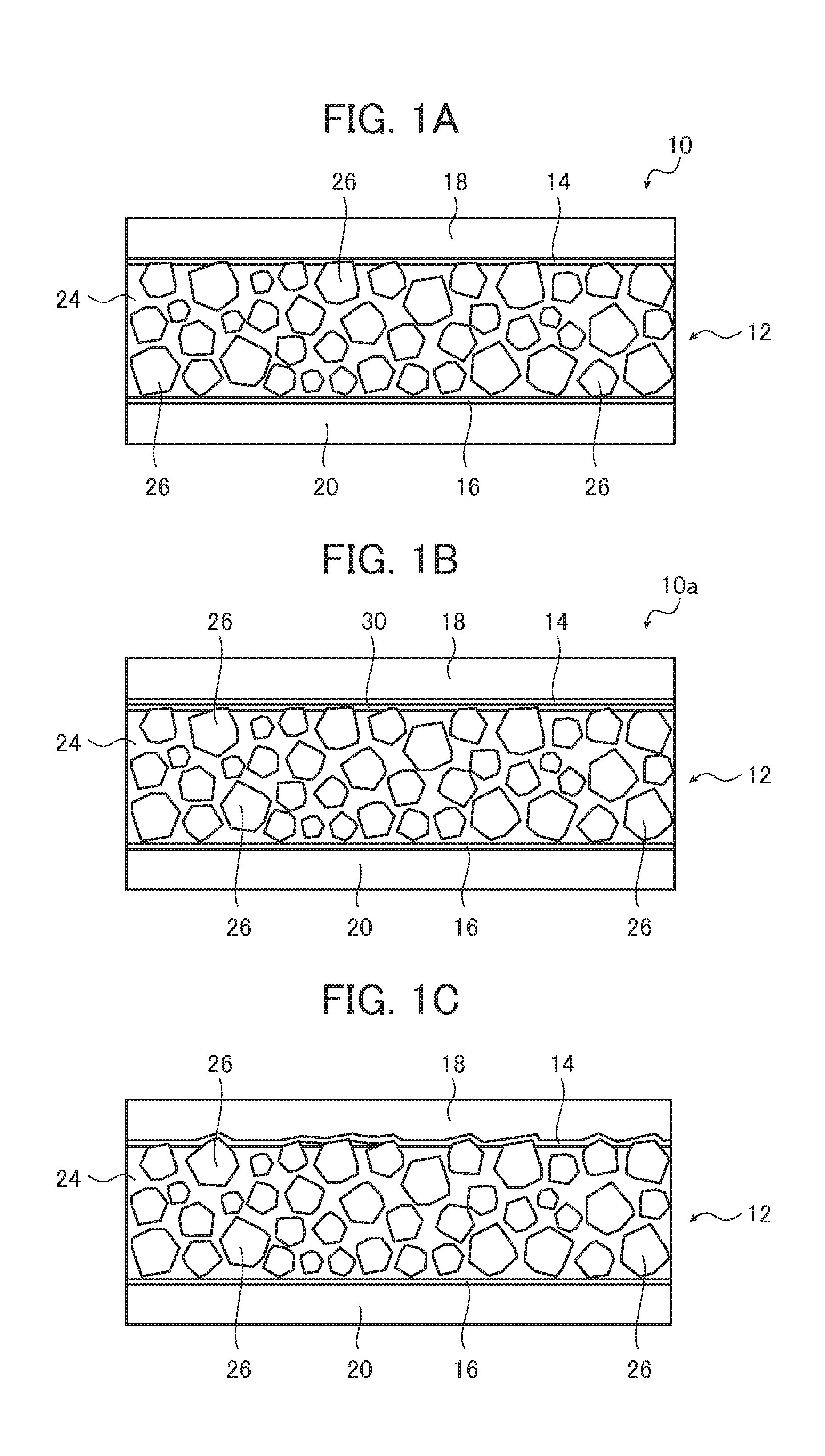
[0216]The transduction film 10 as illustrated in FIG. 1A was prepared by the same method as that in Example 1 except that the calender processing was performed first, and then the polarization processing was performed by reversing the order of the polarization processing and the calender processing.
[0217]In this transduction film 10, as with Example 1, the protective layer 18 and the thin film electrode 14 were peeled off, and the area fraction of the piezoelectric body particles 26 in the surface of the piezoelectric layer 12 (the contact surface with respect to the thin film electrode 14), the arithmetic average surface roughness Ra, the maximum valley depth Rv, and the maximum height roughness Rz of the surface of the piezoelectric layer 12 were measured.
[0218]As a result thereof, the area fraction of the piezoelectric body particles 26 was 42%, the arithmetic average surface roughness Ra was 0.8 μm, the maximum valley depth Rv was 5.6 μm, and the maximum height roughness Rz was ...
example 3
[0222]The transduction film 10a illustrated in FIG. 1B was prepared by the same method as that in Example 2 except that the sheet-like material 38 in which the adhesive layer 30 was formed on the surface of the thin film electrode 14 was used.
[0223]Furthermore, the adhesive layer 30 was formed by using a coating in which 30 parts by weight of cyanoethylated PVA was dissolved in 70 parts by weight of DMF, by applying this coating onto the thin film electrode 14 of the sheet-like material 38, by heating and drying the coating on a hot plate at 120° C., and by evaporating DMF.
[0224]The thickness of the adhesive layer 30 was approximately 1 μm.
[0225]In this transduction film 10a, as with Example 1, the protective layer 18 and the thin film electrode 14 were peeled off, and the area fraction of the piezoelectric body particles 26 in the surface of the adhesive layer 30 (the contact surface with respect to the thin film electrode 14) was measured. After measuring the area fraction, the ad...
PUM
 Abstract
Description
Claims
Application Information
 - R&D
- Intellectual Property
- Life Sciences
- Materials
- Tech Scout
- Unparalleled Data Quality
- Higher Quality Content
- 60% Fewer Hallucinations
Browse by: Latest US Patents, China's latest patents, Technical Efficacy Thesaurus, Application Domain, Technology Topic, Popular Technical Reports.
© 2025 PatSnap. All rights reserved.Legal|Privacy policy|Modern Slavery Act Transparency Statement|Sitemap|About US| Contact US: help@patsnap.com


