Vehicle power management device

a power management device and vehicle technology, applied in secondary cells, servicing/maintenance of batteries, instruments, etc., can solve the problems of short cruising range and further decrease of cruising range, and achieve the effect of suppressing performance degradation (reduction of storage capacity) of the first storage device, reducing internal resistance power loss, and extending the cruising range of the vehicl

Active Publication Date: 2016-01-21
MITSUBISHI ELECTRIC CORP
View PDF4 Cites 17 Cited by
  • Summary
  • Abstract
  • Description
  • Claims
  • Application Information

AI Technical Summary

Benefits of technology

[0010]According to the vehicle power management system according to the present invention, in the case where the drive power consumption increases, the vehicle power management device stops the DC voltage conversion and output device to stop power supply from the first storage device to the electrical loads, and thus, by reducing the power loss in internal resistance of the first storage device, the cruising range of the vehicle can be extended. Furthermore, performance degradation (reduction in storage capacity) of the first storage device can be suppressed, and reduction in travel distance of the vehicle can be suppressed.

Problems solved by technology

Electric vehicles, however, have a short cruising range of approximately 100 km to 200 km when they are in full charge as the energy density of batteries for electric vehicles is lower than that of gasoline, and the cruising range further decreases through power consumption by electrical loads such as an air conditioner.

Method used


Image

  • Vehicle power management device
  • Vehicle power management device
  • Vehicle power management device

Examples


embodiment 1

Device Configuration

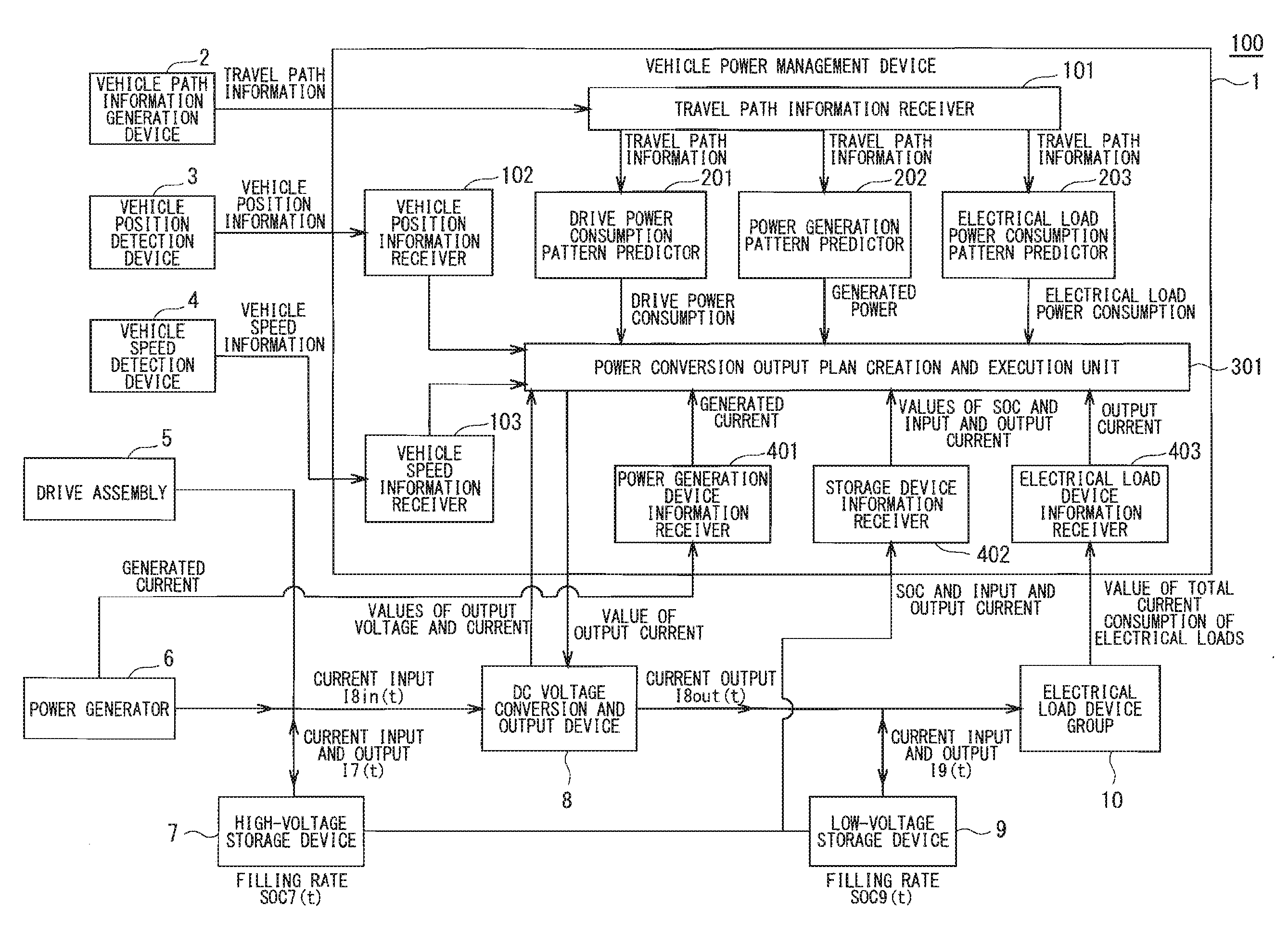
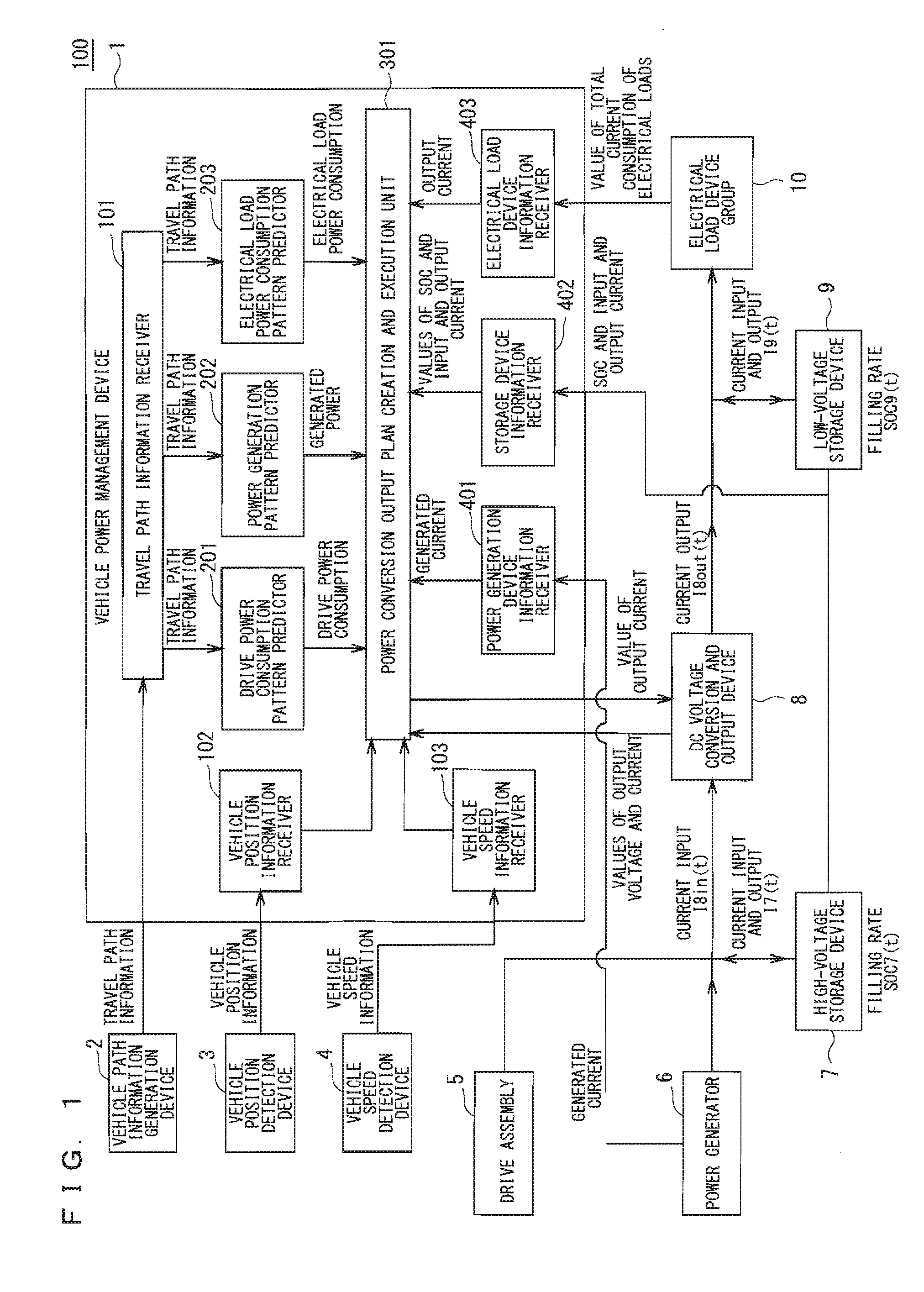
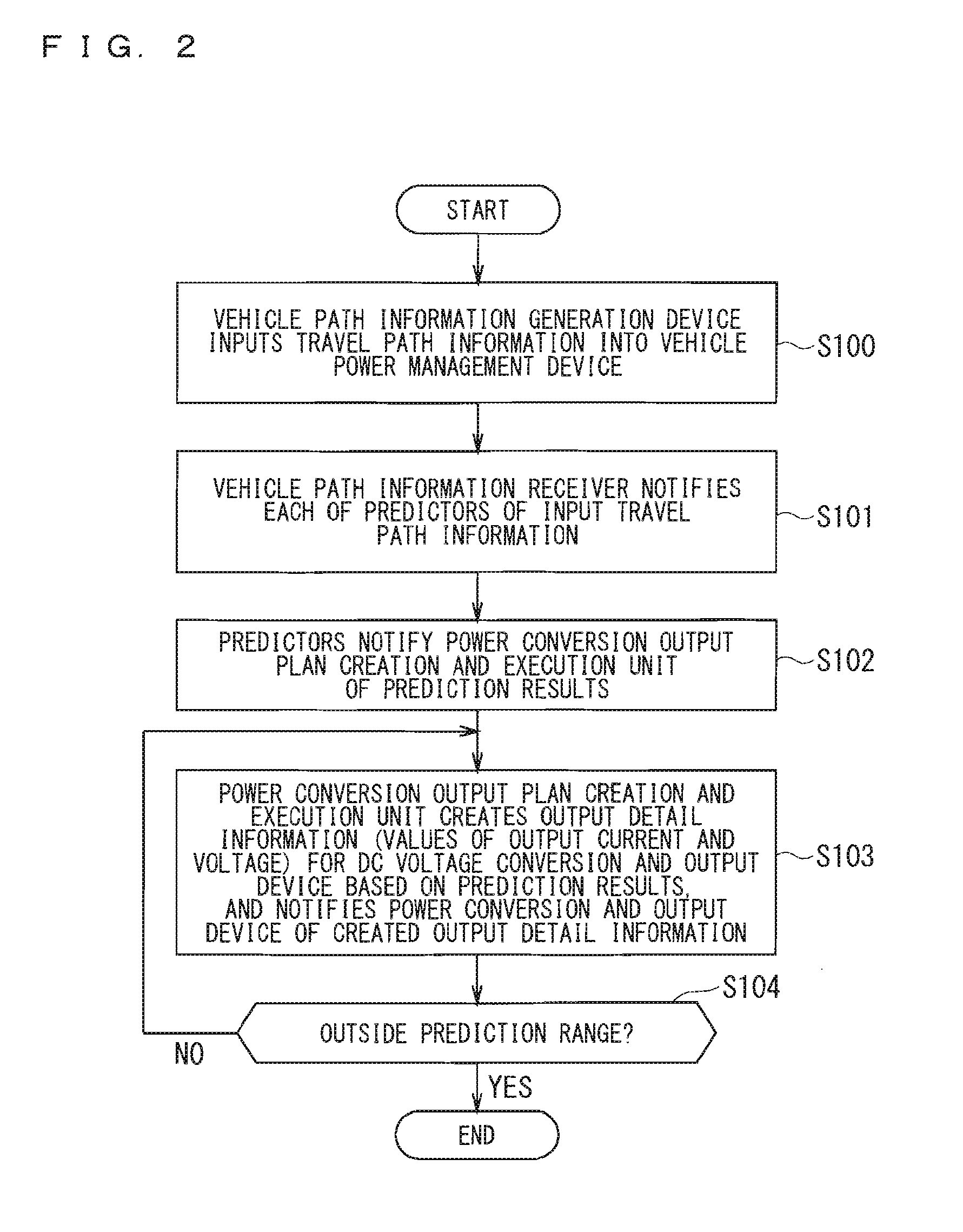
[0020]FIG. 1 is a block diagram showing the configuration of a vehicle power management system 100 in Embodiment 1 according to the present invention.

[0021]The vehicle power management system 100 shown in FIG. 1 includes a vehicle power management device 1, a vehicle path information generation device 2, a vehicle position detection device 3, a vehicle speed detection device 4, a drive assembly 5, a power generator 6, a high-voltage storage device 7, a DC voltage conversion and output device 8, a low-voltage storage device 9, and an electrical load device group 10. The vehicle power management device 1 controls the flow of electric energy in the vehicle. The vehicle path information generation device 2 generates and outputs a travel path of the vehicle. The vehicle position detection device 3 detects an absolute position or a relative position of the vehicle, such as the latitude and the longitude of the GPS and an accumulative travel distance. The vehicle speed ...

embodiment 2

[0066]A vehicle power management system in Embodiment 2 according to the present invention is described next. The vehicle power management system in Embodiment 2 has the same configuration as the vehicle power management system 100 shown in FIG. 1, and FIGS. 1 and 3, which are used in description of Embodiment 1, are also used in description of Embodiment 2. Embodiment 2 is based on the premise that the power conversion output plan creation and execution unit 301 can acquire the timing of power generation and the value of power (the value of current) generated by the power generator 6 from the power generator information receiver 401, as in Embodiment 1.

[0067]In Embodiment 1, in the case where output of the high-voltage storage device 7 is equal to or larger than a predetermined value, power supply from the high-voltage storage device 7 to a low-voltage side is stopped to suppress the power loss caused by the internal resistance of the high-voltage storage device 7 and other factors...

embodiment 3

[0087]A vehicle power management system in Embodiment 3 according to the present invention is described next. The vehicle power management system in Embodiment 3 has the same configuration as the vehicle power management system 100 shown in FIG. 1, and FIGS. 1 and 3, which are used in description of Embodiment 1, are also used in description of Embodiment 2.

[0088]In Embodiment 1, power supply from the high-voltage storage device 7 to the low-voltage side is stopped in the case where output of the high-voltage storage device 7 is equal to or larger than the predetermined value to suppress the power loss caused by the internal resistance of the high-voltage storage device 7 and other factors, and, in Embodiment 2, the power loss caused when the storage device is charged with power generated by the power generator 6 is suppressed, but a power conversion loss caused in the DC voltage conversion and output device 8 is not sufficiently suppressed.

[0089]In Embodiment 3, a method for reduci...


PUM

PropertyMeasurementUnit
voltageaaaaaaaaaa
travel distanceaaaaaaaaaa
poweraaaaaaaaaa

Abstract

A vehicle power management device managing: a vehicle path information generation device generating a vehicle travel path: a drive assembly consuming power to drive the vehicle; a power generator; an electrical load device group; a high-voltage storage device storing power for driving the vehicle; a low-voltage storage device storing power for operating the electrical load device group; and a DC voltage conversion and output device converting voltage of power stored in the high-voltage storage device to generate DC voltage for operating the electrical load device group, and outputting the DC voltage, and controlling electric energy flow in the vehicle. The vehicle power management device controls output of the DC voltage conversion and output device so that a filling rate of the low-voltage storage device is between lower and upper limits of a range in which a charge and discharge speed is equal to or higher than a predetermined value.

Description

TECHNICAL FIELD[0001]The present invention relates to a vehicle power management system for managing power for driving electrical loads in a vehicle.BACKGROUND ART[0002]In recent years, electric vehicles powered by electric energy have been put into practical use to reduce carbon dioxide emissions and achieve efficient utilization of energy. Electric vehicles, however, have a short cruising range of approximately 100 km to 200 km when they are in full charge as the energy density of batteries for electric vehicles is lower than that of gasoline, and the cruising range further decreases through power consumption by electrical loads such as an air conditioner.[0003]To solve this problem, technology for promoting energy saving in the electrical loads in the electric vehicles to reduce power consumption during traveling and to thereby extend the cruising range has been proposed.[0004]As such technology, Patent Document 1 discloses a vehicle power system that calculates a market price of...

Claims


Application Information

Patent Timeline
Patent Type & Authority Applications(United States)
IPC IPC(8): B60L11/18B60L1/00B60L50/10B60W10/08B60W10/26B60W50/00H01M10/44
CPCB60L11/1862B60L1/00B60W10/08B60W10/26H01M2220/20H01M10/44B60L11/02H01M2010/4271B60W50/0097H02J7/34H01M10/425B60L2240/545Y02T10/70B60L50/10B60L58/13H02J2310/48Y02T10/7072Y02E60/10H02J7/0013
Inventor IGARASHI, YUJIKAWAI, KATSUYAGOTO, YUKIOTANIMOTO, MASAHIKONISHITA, YOSHITOSHIRASAWA, KAZUSHIMATSUNAGA, TAKANORISUGIYAMA, AKINOBU
Owner MITSUBISHI ELECTRIC CORP
Why Eureka
Try Eureka