Polarization plate, method for manufacturing same, and image display device

Inactive Publication Date: 2016-01-21
FUJIFILM CORP
View PDF4 Cites 15 Cited by
  • Summary
  • Abstract
  • Description
  • Claims
  • Application Information

AI Technical Summary

Benefits of technology

[0023]According to the present invention, it is possible to provide a polarization plate in

Problems solved by technology

In particular, as disclosed in JP2012-048181A, it was not known in the related art that the problem of the occurrence of curling was not able to be suf

Method used


Image

  • Polarization plate, method for manufacturing same, and image display device
  • Polarization plate, method for manufacturing same, and image display device
  • Polarization plate, method for manufacturing same, and image display device

Examples


Example

Manufacturing Example 1

Preparation of First Protective Film

[0251]

[0252](Raw Material Polyester 1)

[0253]As described below, a raw material polyester 1 (Sb catalyst-based PET) was obtained by a continuous polymerization device using a direct esterification method in which a terephthalic acid directly reacted with ethylene glycol, water was removed from the reactant, and the reactant was esterified, and then was subjected to polycondensation under reduced pressure.

[0254](1) Esterification Reaction

[0255]4.7 tons of a high purity terephthalic acid and 1.8 tons of ethylene glycol were mixed for 90 minutes in order to form slurry, and were continuously supplied to a first esterification reactor at a flow rate of 3800 kg / h. Further, an ethylene glycol solution of antimony trioxide was continuously supplied to the reactor, and a reaction was performed under stirring at a temperature of 250° C. in the reactor for an average retention time of approximately 4.3 hours. At this time, the antimony...

Example

Manufacturing Example 2

Stretched PET 80 μm

[0285]A PET film (hereinafter, referred to as stretched PET 80 μm) having retardation Re in the in-plane direction of 8100 nm, and retardation Rth in the film thickness direction of 9300 nm was manufactured by the same method as that in Manufacturing Example 1 except that the thickness of the completed film was 80 μm.

Example

Manufacturing Example 3

Stretched PET 60 μm

[0286]A PET film (hereinafter, referred to as stretched PET 60 μm) having retardation Re in the in-plane direction of 6100 nm, and retardation Rth in the film thickness direction of 6900 nm was manufactured by the same method as that in Manufacturing Example 1 except that the thickness of the completed film was 60 μm.


PUM

PropertyMeasurementUnit
Temperatureaaaaaaaaaa
Fractionaaaaaaaaaa

Abstract

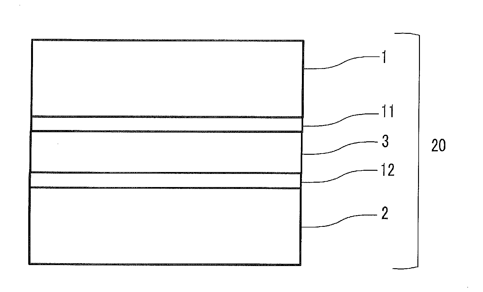
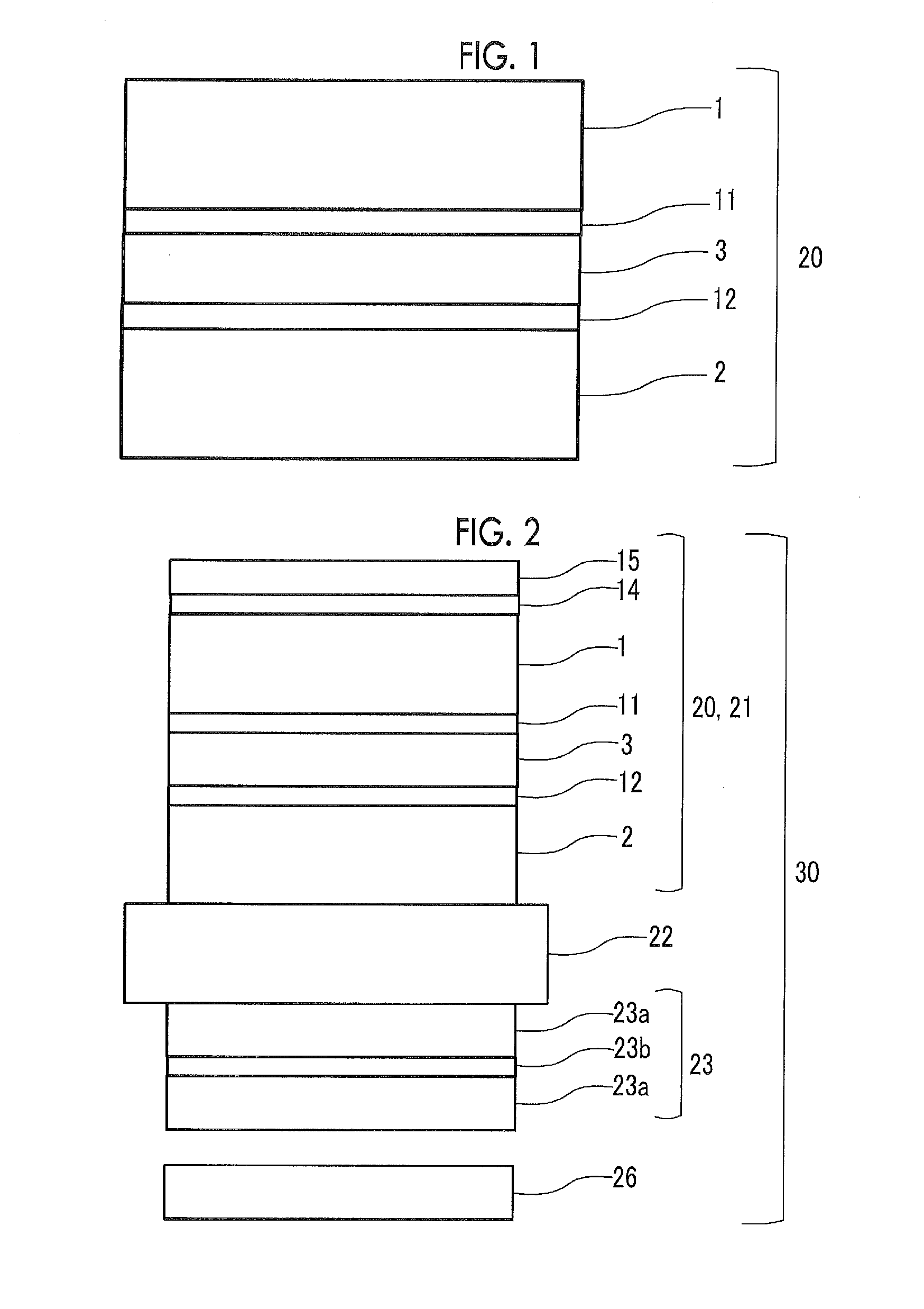
A polarization plate includes a polarizer having polarization performance; a first protective film bonded to one surface of the polarizer through an adhesive layer 1; and a second protective film bonded to the other surface of the polarizer through an adhesive layer 2, in which a modulus of elasticity of the first protective film at 25° C. and relative humidity of 60% in an absorption axis direction of the polarizer is greater than or equal to 1.0 GPa and less than 4.0 GPa, a ratio of the modulus of elasticity of the first protective film at 25° C. and relative humidity of 60% in the absorption axis direction of the polarizer to a modulus of elasticity of the first protective film at 25° C. and relative humidity of 60% in a direction orthogonal to the absorption axis of the polarizer is less than or equal to 0.8, a modulus of elasticity of the second protective film at 25° C. and relative humidity of 60% in the absorption axis direction of the polarizer is greater than or equal to 2.0 GPa and less than 5.0 GPa, and (Expression 1) and (Expression 2) described below are satisfied, suppresses curling of the polarizer in the absorption axis direction (d1 and d2 are thicknesses of the first protective film and the second protective film (unit: μm)).
d2/d1≦0.8;  (Expression 1)
d2≦40 μm  (Expression 2)

Description

CROSS-REFERENCE TO RELATED APPLICATIONS[0001]This application is a Continuation of PCT International Application No. PCT / JP2014 / 060814, filed on Apr. 16, 2014, which claims priority under 35 U.S.C. Section 119(a) to Japanese Patent Application No. 2013-088799 filed on Apr. 19, 2013. Each of the above applications is hereby expressly incorporated by reference, in its entirety, into the present application.BACKGROUND OF THE INVENTION[0002]1. Field of the Invention[0003]The present invention relates to a polarization plate, a method for manufacturing the same, and an image display device.[0004]2. Description of the Related Art[0005]In an image display device such as a liquid crystal display (LCD), a plasma display (PDP), an electroluminescence display (OELD or IELD), a field emission display (FED), a touch panel, and an electronic paper, a polarization plate is arranged on a display screen side of an image display panel. For example, a liquid crystal display device has been variously u...

Claims


Application Information

Patent Timeline
IPC IPC(8): G02B5/30G02B1/14
CPCG02B1/14G02B5/305G02F1/133528G02F1/0072G02F2201/50B32B7/12B32B2307/42B32B2307/51B32B2457/20
Inventor YONEMOTO, TAKASHIYAMADA, NAOYOSHIFURUKAWA, HIROMICHISANETO, RYUJIHISANAGA, KAZUYA
Owner FUJIFILM CORP
Why Eureka
Try Eureka