
Cooling system for stored nuclear fuel

Inactive Publication Date: 2016-01-21
THE FUJIKURA CABLE WORKS LTD
View PDF6 Cites 2 Cited by
  • Summary
  • Abstract
  • Description
  • Claims
  • Application Information

AI Technical Summary

Benefits of technology

The present invention is a cooling system for nuclear fuel that prevents water level decrease due to evaporation. The system uses a heat exchanger called heat pipe, which cools the nuclear fuel by drawing heat from the lower layer of cooling water. This prevents damage to the heat pipe and ensures continuous cooling. The cooling water is divided into three layers, and it can be brought into direct contact with the lower end of the heat pipe to reduce thermal resistance and cool the nuclear fuel more efficiently. The system can maintain the water level in the pool and prevent evaporation, even without an external power supply.

Problems solved by technology

Therefore, it cannot be applied to the storing facility of the spent nuclear fuel to be conveyed or rejected.
Likewise, since the solar pond taught by WO 02 / 073099 is adapted to store the solar heat therein, it cannot be applied to the cooling system of the spent nuclear fuel developing heat inevitably.

Method used


Image

  • Cooling system for stored nuclear fuel
  • Cooling system for stored nuclear fuel
  • Cooling system for stored nuclear fuel

Examples


Embodiment Construction

)

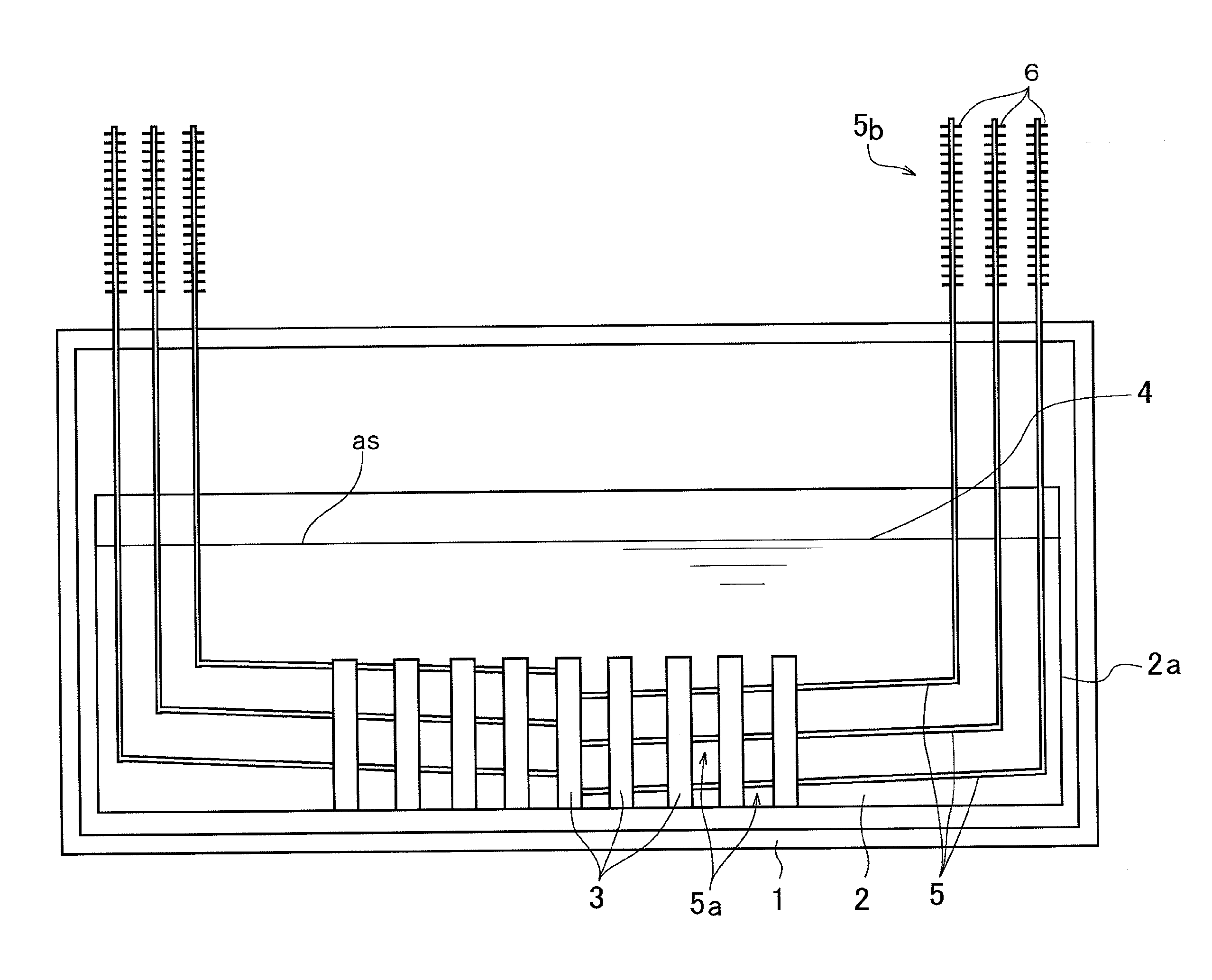
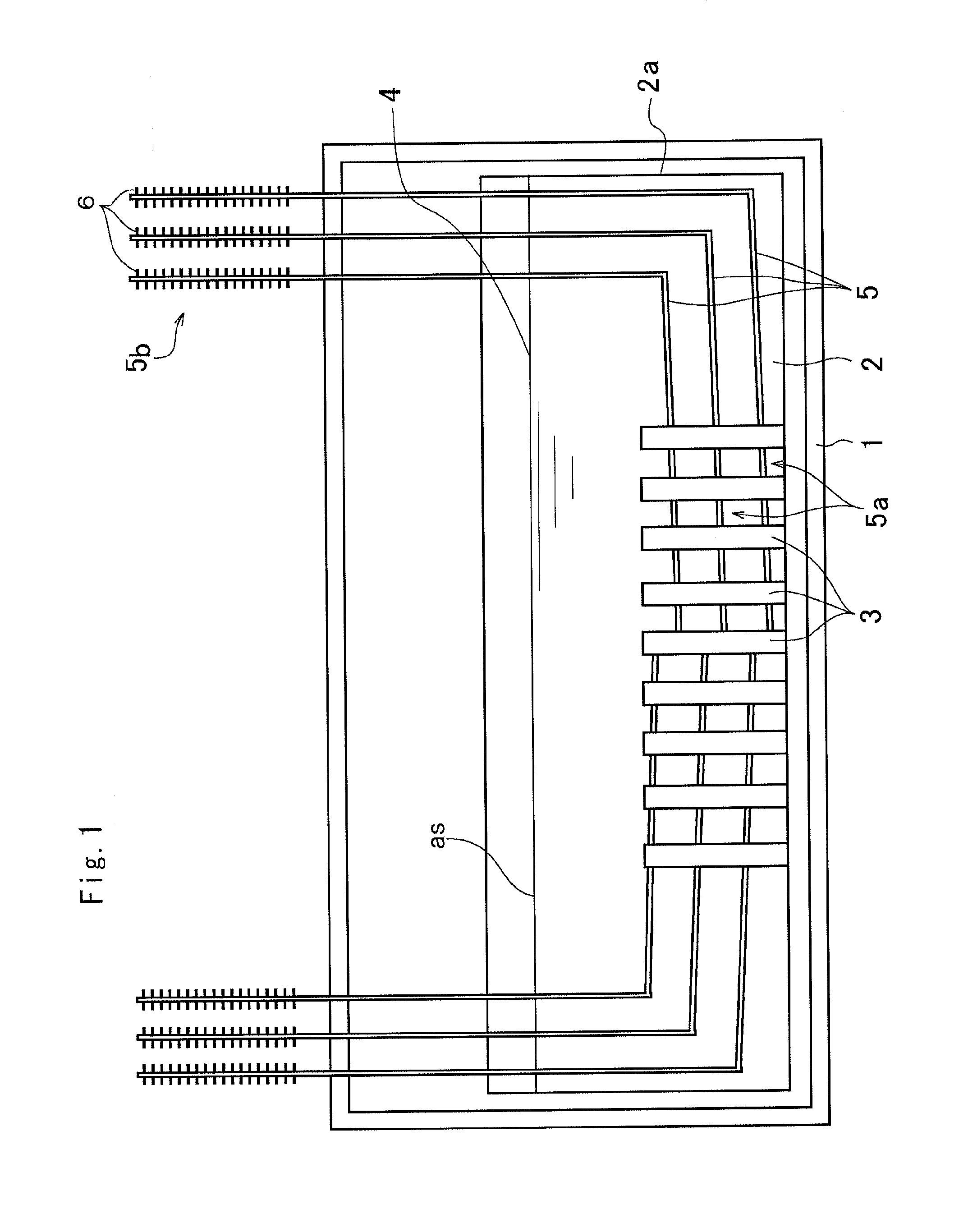
[0024]Preferred examples of the present invention will be explained hereinafter. Referring now to FIG. 1, there is shown one example of the cooling system for stored nuclear fuel having a housing 1 and a pool 2 arranged therein. Specifically, the housing 1 is a closed chamber that is normally closed to be insulated from outside. For example, a frame 2a of the pool 2 is formed of concrete, and filled with ample amount of cooling water 4 to immerse nuclear fuel 3 held in a not shown rack. The nuclear fuel 3 includes both spent nuclear fuel and unspent nuclear fuel, and the nuclear fuel 3 is stored at a bottom of the pool 2. In the example shown in FIG. 1, one ends (i.e., lower ends) 5a of heat pipes 5 are situated around the nuclear fuels 3, and other ends (i.e., upper ends) 5b of the heat pipes 5 are situated outside of the housing (to be exposed to the external air). In order to enlarge radiation area, a plurality of fins 6 are arranged on the other end 5b of each heat pipe 5. Thus...


PUM


Abstract

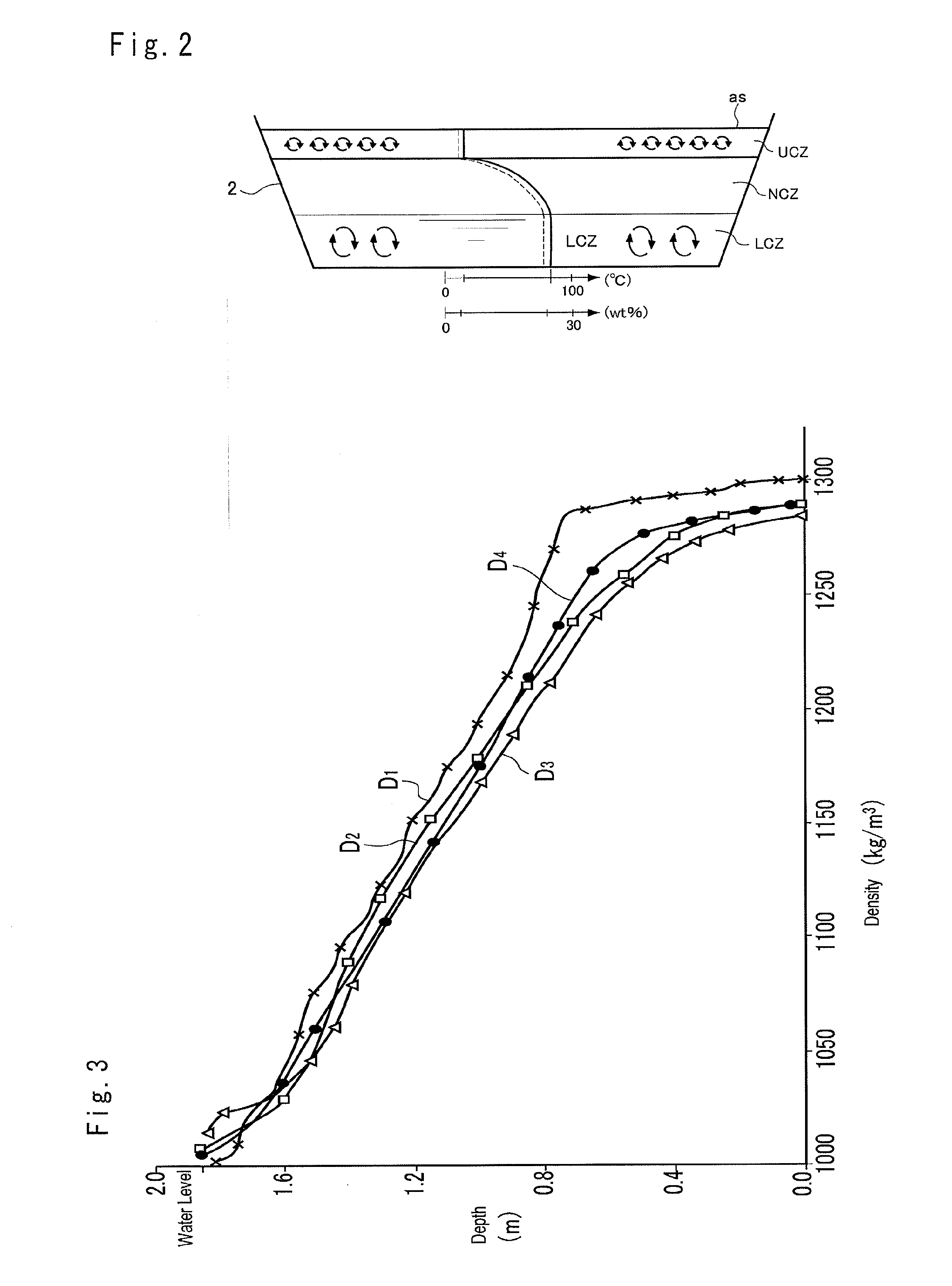
A cooling system for cooling nuclear fuel stored in a pool that can prevent a lowering of water level resulting from evaporation is provided. The cooling system cools the nuclear fuels 3 stored in a bottom of the pool 2 filled with cooling water 4. The cooling water 4 comprises an upper layer formed in a water surface as side in which a density of the cooling water 4 is low, a lower layer formed in the bottom side of the pool 2 in which a density of the cooling water 4 is high, and an intermediate layer in which a density of the cooling water 4 is in between those of the cooling waters 4 in the upper layer and the lower layer. A lower end 5a of a heat pipe 5 adapted to transport heat in the form of latent heat of working fluid is situated at a site where the heat is exchanged with the cooling water 4, and an upper 5b end of the heat pipe 5 is exposed to external air. The nuclear fuel 3 is stored within the lower layer.

Description

TECHNICAL FIELD[0001]This invention relates to a system for cooling nuclear fuel stored in a cooling pool by radiating decay heat of the nuclear fuel.BACKGROUND ART[0002]Japanese Patent Laid-Open No. 11-183695 describes one example of the system of this kind. In the facility taught by Japanese Patent Laid-Open No. 11-183695, a main body is held on a floating structure floating on the ocean, and an outer face of the main body is cooled by the ocean water. The main body is divided by a partition wall into an upper spent fuel pool and a lower coolant pool. The spent fuel is held in a storage pipe in which an upper end is fixed to the partition wall and a lower end is immersed in the coolant so that the coolant warmed by the spent fuel can be cooled by exchanging heat indirectly with the ocean water. Thus, according to the teachings of Japanese Patent Laid-Open No. 11-183695, the spent fuel can be stored on the ocean while being cooled.[0003]Facilities for cooling the nuclear fuel by tr...

Claims


Application Information

Patent Timeline
IPC IPC(8): G21C19/32G21C19/07G21F5/10
CPCG21C19/32G21F5/10G21C19/07G21F9/36F28D15/0275F28D2015/0216G21C19/08Y02E30/30
Inventor MOCHIZUKI, MASATAKARANDEEP, SINGHMATSUDA, MASAHIRO
Owner THE FUJIKURA CABLE WORKS LTD
Learn More