Control circuit implementing a related method for controlling a switching power factor corrector, a pfc and an ac/dc converter

a control circuit and switching power factor technology, applied in the direction of ac-dc conversion, ac-dc regulation, efficient power electronics conversion, etc., can solve the problems of increasing harmonic distortion in discontinuous current mode (dcm), low efficiency of constant frequency average current mode control at light load, and wide switching frequency variation with rms input voltage range and input voltage conduction angle, etc., to achieve simple, low-cost full analog circuit implementation

Active Publication Date: 2016-01-21
STMICROELECTRONICS SRL
View PDF6 Cites 23 Cited by
  • Summary
  • Abstract
  • Description
  • Claims
  • Application Information

AI Technical Summary

Benefits of technology

[0010]One embodiment of the present disclosure provides a power factor correction device for switching power supplies working in CCM which overcomes the above draw

Problems solved by technology

The constant frequency average current mode control has also a very low efficiency at light load due to high switching losses.
Besides, average current mode controllers present a non-linear characteristic at light load that increases harmonic distortion in discontinuous current mode (DCM) operation.
A drawback of these devices is the very wide switching frequency variation with rms input voltage range and input voltage conduction angl

Method used


Image

  • Control circuit implementing a related method for controlling a switching power factor corrector, a pfc and an ac/dc converter
  • Control circuit implementing a related method for controlling a switching power factor corrector, a pfc and an ac/dc converter
  • Control circuit implementing a related method for controlling a switching power factor corrector, a pfc and an ac/dc converter

Examples


Embodiment Construction

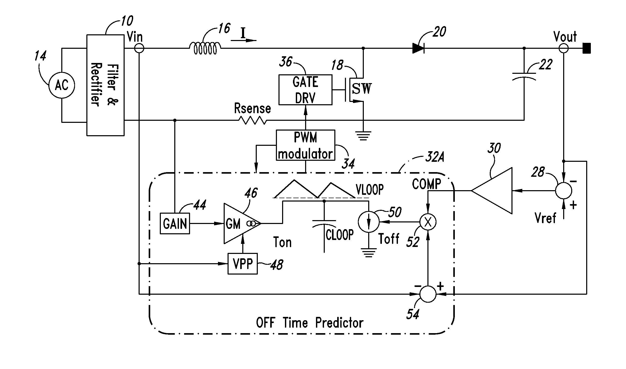
[0033]An AC / DC switching converter, including a rectifier and filter circuit 10 and a PFC 12A according to an exemplary embodiment of this disclosure, is depicted in FIG. 3. The AC input voltage from the mains 14 is rectified and filtered by the rectifier and filter circuit 10, which includes a rectifying bridge and an input filter for obtaining a rectified input voltage Vin. The PFC 12A includes an inductor 16, a power switch 18, an output diode 20, an output capacitor 22, a sense resistor 24, and a closed-loop control circuit 26. The control loop 26 receives the output voltage Vout, the input voltage Vin and a current sense signal Isense, and provides a signal for turning on / off the switch 18. The current sense signal Isense represents the current flowing through the switch SW during on-time intervals and is generated with a sense resistor Rsense.

[0034]The control loop 26 includes a subtractor 28, configured to determine the difference between a reference voltage Vref and the outp...


PUM


Abstract

A control circuit controls a switching power factor corrector based on switch off-time modulation by controlling the input electric charge during on-time. The circuit includes a charge current generator that generates charge current as a replica of a current sense signal amplified with a gain corresponding to the square of peak value of a rectified input voltage, a loop capacitor charged with the charge current during on-time intervals and discharged with a discharge current during off-time intervals, a discharge current generator that generates the discharge current proportional to a product of a comparison voltage and a difference between a regulated output voltage and the rectified input voltage, and a PWM modulator that senses a charge voltage of the loop capacitor, turns on the switch for an on-time duration in response to detecting that the charge voltage nullifies, and turns off the switch when the on-time duration has elapsed.

Description

BACKGROUND[0001]1. Technical Field[0002]The present disclosure relates to power converter circuits, in particular to a control circuit implementing a related method for controlling a switching power factor corrector (PFC), a PFC and an AC / DC converter including the PFC.[0003]2. Description of the Related Art[0004]Many electronic devices, such as computers, TV sets, etc. or rechargeable batteries, use a DC voltage as supply voltage, thus the AC voltage made available by the mains is AC / DC converted. Especially in cases in which the power consumption of the supplied load is relatively great, a power factor correction is used to minimize reactive power and to maximize real power absorbed from the mains. In this case, an AC / DC converter that provides power factor correction includes a power factor corrector (PFC) and eventually a DC / DC converter in cascade to the PFC.[0005]A PFC of the type shown in FIG. 1 usually comprises a bridge rectifier that rectifies the mains voltage and generat...

Claims


Application Information

Patent Timeline
IPC IPC(8): H02M1/42H02M1/00
CPCH02M1/4208H02M1/4225G05F1/61Y02B70/10H02M1/0054
Inventor CASTELLI, CLAUDIA
Owner STMICROELECTRONICS SRL
Why Eureka
Try Eureka