Automated deflectometry system for assessing reflector quality

a technology of automatic deflectometry and reflector quality, which is applied in the direction of reflective surface testing, instruments, image enhancement, etc., can solve the problems of preventing the use of the receiver as a quality checking system in high-volume manufacturing, affecting the accuracy of the reflector, and unable to unambiguously identify the quality of the reflector

Inactive Publication Date: 2016-01-28
AALBORG CSP AS
View PDF5 Cites 16 Cited by
  • Summary
  • Abstract
  • Description
  • Claims
  • Application Information

AI Technical Summary

Benefits of technology

[0045]Because the method of differential image reconstruction is used on each measured reflector individually, the system according to the fourth embodiment does not require a calibration surface or a surface specially fabricated to have an ideal slope profile.

Problems solved by technology

Large variations from a desired surface profile (e.g. flat or curved)slope amongst many reflectors in a field can hinder the supply of requisite flux to the receiver, as the amount of light reflected from the heliostats may not comply with expected results garnered from simulations and calculations by plant operators.
Even amongst deflectometry solutions there exist drawbacks that hinder its use as a quality checking system in high-volume manufacturing.
Finally, conventional deflectometer techniques do not possess the capability to unambiguously identify specific features in a reflected pattern if the pattern comprises repeated sections.

Method used


Image

  • Automated deflectometry system for assessing reflector quality
  • Automated deflectometry system for assessing reflector quality
  • Automated deflectometry system for assessing reflector quality

Examples


first embodiment

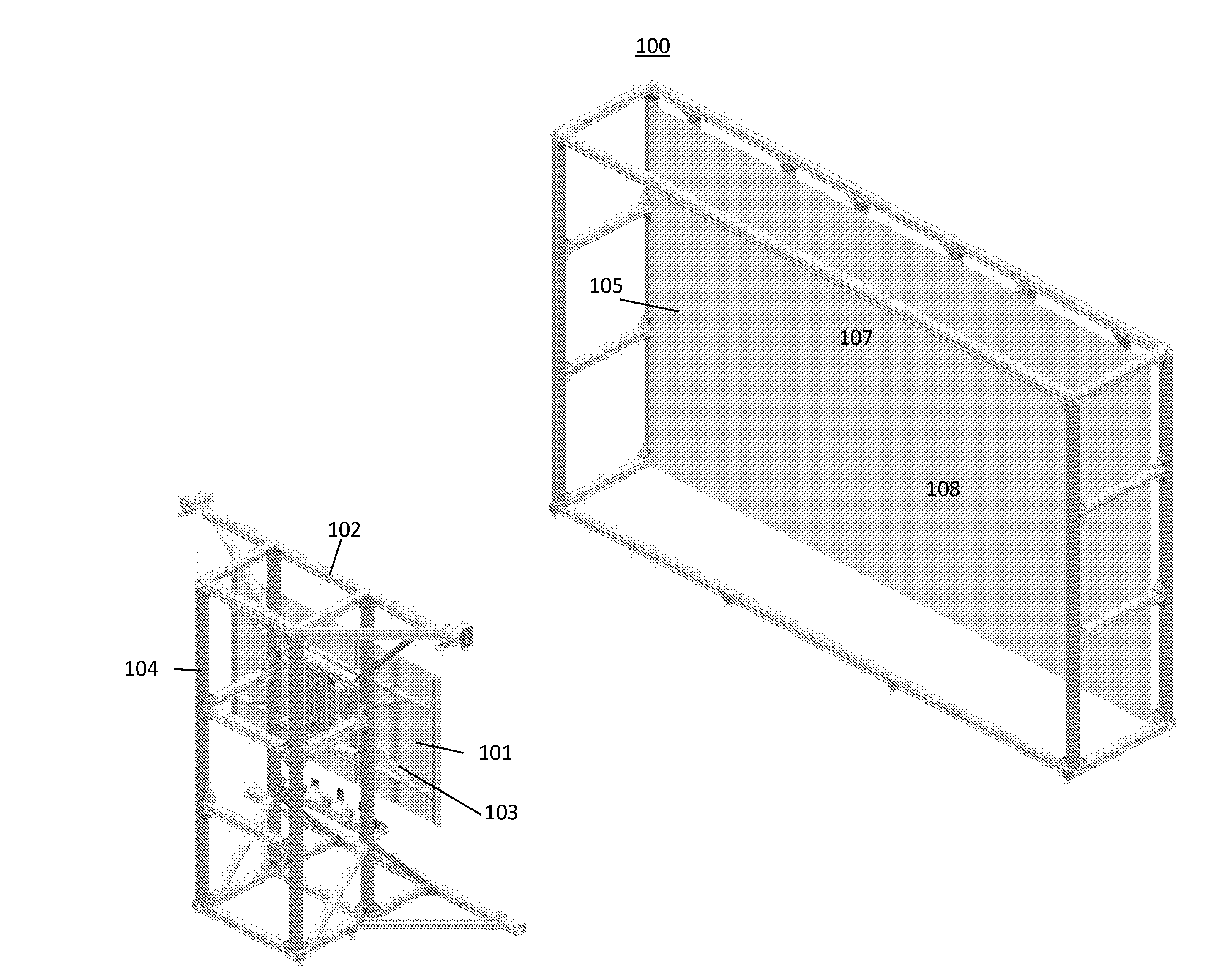
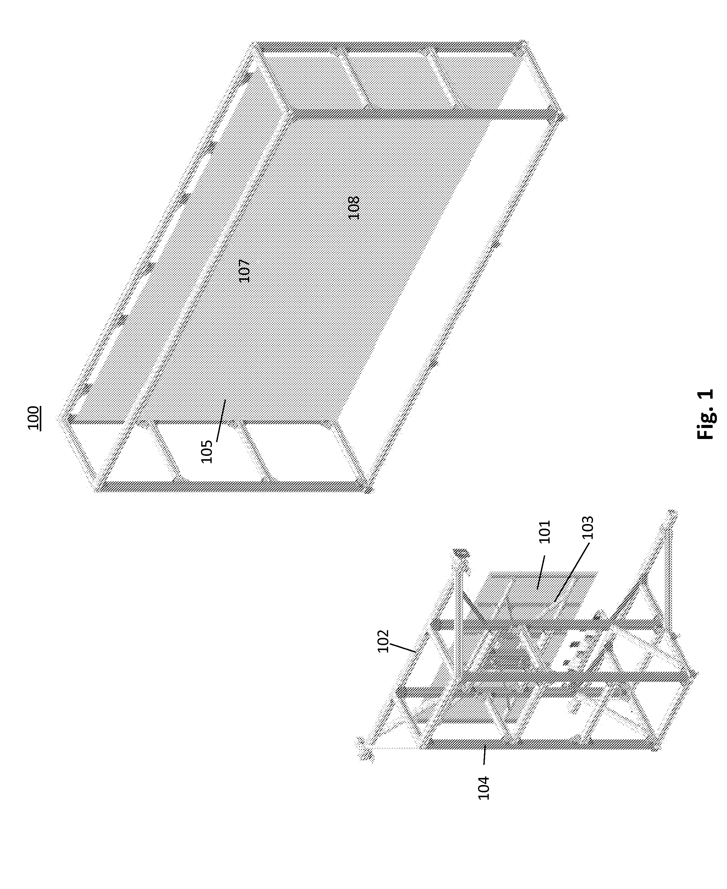
[0065]FIG. 7 is a detailed flowchart depiction of a method (730) for assessing the quality of a reflector using the present invention, wherein the method comprises the following steps:[0066]1) Setup the automated deflectometry system according to the embodiment depicted in FIG. 1, wherein the calibration surface has a known surface quality and has a larger mirror area than the mirror area of the reflective surface to-be-measured,[0067]2) Commission the holding fixture and target screen to be parallel to each other at a predetermined distance apart,[0068]3) Calibrate the digital cameras,[0069]4) Overlay a template having the same dimensions as the reflective surface onto the calibration surface,[0070]5) Mount the calibration surface onto the holding fixture,[0071]6) Take an image of the calibration surface with each camera,[0072]7) Determine the coordinates of the corners of the template using the image processing software,[0073]8) Locate the features of the known pattern in the imag...

second embodiment

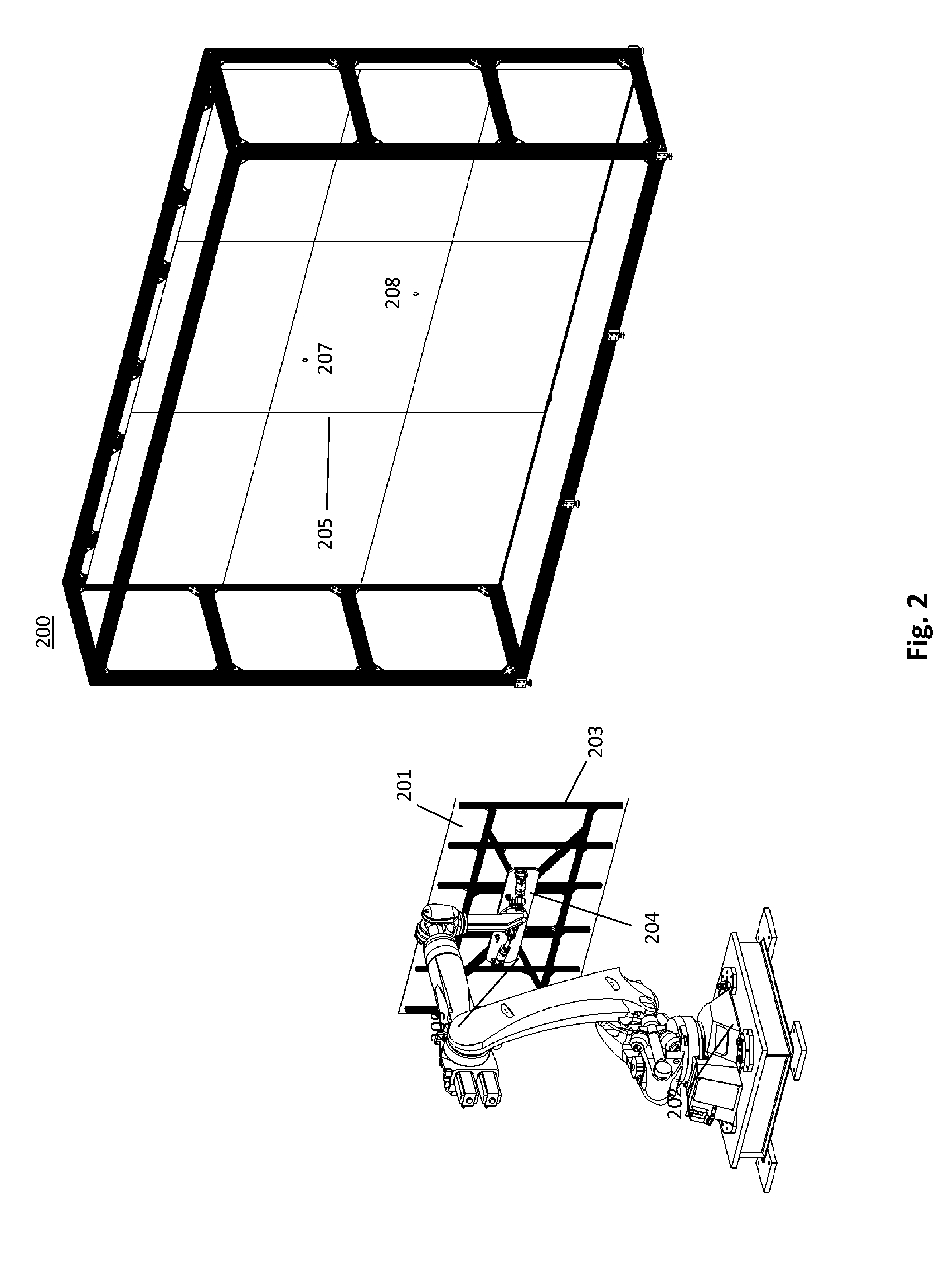
[0080]FIG. 8 is a detailed flowchart depiction of a method (830) for assessing the quality of a reflector using the present invention, wherein the method comprises the following steps:[0081]1) Setup the automated deflectometry system according to the embodiment depicted in FIG. 2, wherein the calibration surface has an unknown surface quality and has a larger mirror area than the reflective surface to-be-measured,[0082]2) Commission the holding fixture and target screen to be parallel to each other at a predetermined distance apart,[0083]3) Calibrate the digital cameras,[0084]4) Overlay a template having the same dimensions as the reflective surface onto the calibration surface,[0085]5) Mount the calibration surface onto the holding fixture,[0086]6) Take a first image of the calibration surface with each camera,[0087]7) Translate the calibration surface along a first axis in the plane parallel to the target screen face and take a second image of the calibration surface with each cam...

third embodiment

[0099]FIG. 9 is a detailed flowchart depiction of a method (930) of assessing the quality of a reflector using the present invention, wherein the method comprises the following steps:[0100]1) Setup the automated deflectometry system according to the embodiment depicted in FIG. 2, wherein the calibration surface has a known surface quality and has a mirror area substantially less than the reflective surface to-be-measured,[0101]2) Commission the holding fixture and target screen to be parallel to each other and set a predetermined distance apart.[0102]3) Calibrate the digital cameras,[0103]4) Mount the calibration surface onto the holding fixture,[0104]5) Translate the calibration surface along at least one axis in the plane parallel to the target screen face and take an image of the calibration surface with each camera,[0105]6) Repeat Step 5 until the entirety of the known pattern on the target screen has been captured in reflected images,[0106]7) Using the image processing software...


PUM


Abstract

An automated deflectometry system and method for assessing the quality of a reflective surface for use in a concentrating solar power plant. The deflectometry system comprises a holding fixture for mounting a heliostat reflector opposite a target screen having a known pattern. Digital cameras embedded in the target screen take pictures of the known pattern as reflected in the surface of the reflector. Image processing software then detects the features of the pattern in the reflector images and calculates the slope profile of the reflective surface. The slope field can be calculated by comparing the images of the reflective surface to those of a reference surface. Based on the slope profile of the reflective surface, a ray tracing calculation can be performed to simulate flux as reflected from the reflective surface onto a receiver and a quality metric can be ascribed to the heliostat reflector. The result of the quality assessment can displayed using a graphical user interface on an automated assembly line.

Description

CROSS-REFERENCES TO RELATED APPLICATIONS[0001]The present application claims priority to and the benefit of U.S. Provisional Patent Application No. 62 / 027,746, filed on Jul. 22, 2014, the entire disclosure of which is incorporated herein by reference.BACKGROUND OF THE INVENTION[0002]This disclosure relates generally to an apparatus and method for assessing the quality of a reflector. In particular, the invention relates to an improved deflectometry system for measuring the slope of a reflective surface and predicting its performance as part of a solar-collecting heliostat field.[0003]In Concentrating Solar Power (CSP) plants an array of heliostats reflect sunlight toward a receiver mounted atop a central tower and containing a working fluid. One type of receiver transfers incident radiant energy to the working fluid to produce output high-pressure, high-temperature steam, which can later be fed to a turbine for electrical power generation. Heliostats are generally mounted on the gro...

Claims


Application Information

Patent Timeline
Patent Type & Authority Applications(United States)
IPC IPC(8): G01M11/00G01B11/24G06K9/46G06K9/52G06K9/62G06T7/00G06T7/40G06T7/60H04N17/00
CPCG01M11/005G01B11/24G06T7/0004G06T7/60G06K9/52G06T7/408G06T2207/30108H04N17/002G06K9/6201G06K9/6267G06T7/001G06K9/4604G06K9/4652Y02E10/40F24S23/70F24S2201/00F24S40/90
Inventor RISNER, JEREMYZAVODNY, MAXIMILIAN
Owner AALBORG CSP AS
Why Eureka
Try Eureka