Grid tie charge controller

a charge controller and grid tie technology, applied in the direction of electrochemical generators, secondary cell servicing/maintenance, transportation and packaging, etc., can solve the problems of high cost of high-voltage grid-tie system to get solar back up from high-voltage grid-tie system, gird tie system stops supplying power, etc., to prevent any backflow of energy

Active Publication Date: 2016-01-28
SMITH RICK
View PDF17 Cites 21 Cited by
  • Summary
  • Abstract
  • Description
  • Claims
  • Application Information

AI Technical Summary

Benefits of technology

[0008]The Grid Tie Charge Controller is a unique and safe approach to adding battery back up functionality to a standard high DC voltage solar grid-tie system, allowing no compromises in the go-green high energy efficiency that a high voltage solar grid-tie system delivers. Since the National Electric code discourages battery systems in residential settings from operating at over 48 vdc, present day grid-tie plus solar back up power solutions make use of 48 vdc or less input voltage on grid-tie inverters. Moving, after the fact, to a low voltage grid-tie system to get the solar back up from a high voltage grid-tie system is very expensive. Expensive costs include modifications to the photovoltaic array due to rewiring with larger gauge wire, a new grid-tie inverter needs to be purchased, and a charge controller needs to be purchased, and there still needs to be a system to prioritize between keeping the batteries full and delivering power to the grid. The Grid Tie Charge Controller allows the solar back up functionality to be retrofitted and added to a standard grid-tie system without any changes to the grid-tie system.
[0021]The automatic charge control is preferably configured with transformer isolation to achieve complete electrical isolation between the high voltage, the low voltage, and the IGBT (Insulated Gate Bi-Polar Transistors) drive circuit sections in order to: not conflict with the unknown internal architecture of the grid tie inverter this invention gets paired with, eliminating possible ground fault tripping, or worse yet, a potential short circuit; insure compatibility with negative or positive ground off grid side equipment; eliminate the possibility that an IGBT drive circuit failure would result in an IGBT being “stuck on”.
[0023]The automatic charge control preferably further includes a diode at the high voltage DC input to prevent any backflow of power to existing solar array or to the existing grid tie inverter. The automatic charge control further includes a low voltage output that is both diode and circuit breaker protected to both prevent any back flow of energy, and protected against large battery currents flowing in the event of an internal circuit failure. The automatic charge control further includes a secondary voltage sensing relay that unlatches a control relay that has been latched up on its own contacts, permanently dropping the IGBT drive signal until a human can investigate the reason for the “control failure” that allowed the high-high battery voltage condition, wherein the grid tied charge controller system is restarted when a user pushes the start button after the battery voltage is down into an acceptable range. The automatic charge control further includes a separate circuit for sensing battery voltage right at the battery terminals so that decision point voltages are not distorted voltage drop in the main power leads that carry large amounts of current on the low voltage off grid side.

Problems solved by technology

Commonly, gird tie systems stop supplying power when the utility power fails.
Utility power failure when a user needs and expects the photovoltaic system to maintain the household current.
In the event of a power failure, the protected loads will begin drawing power out of the batteries.
Moving, after the fact, to a low voltage grid-tie system to get the solar back up from a high voltage grid-tie system is very expensive.

Method used


Image

  • Grid tie charge controller
  • Grid tie charge controller
  • Grid tie charge controller

Examples


Embodiment Construction

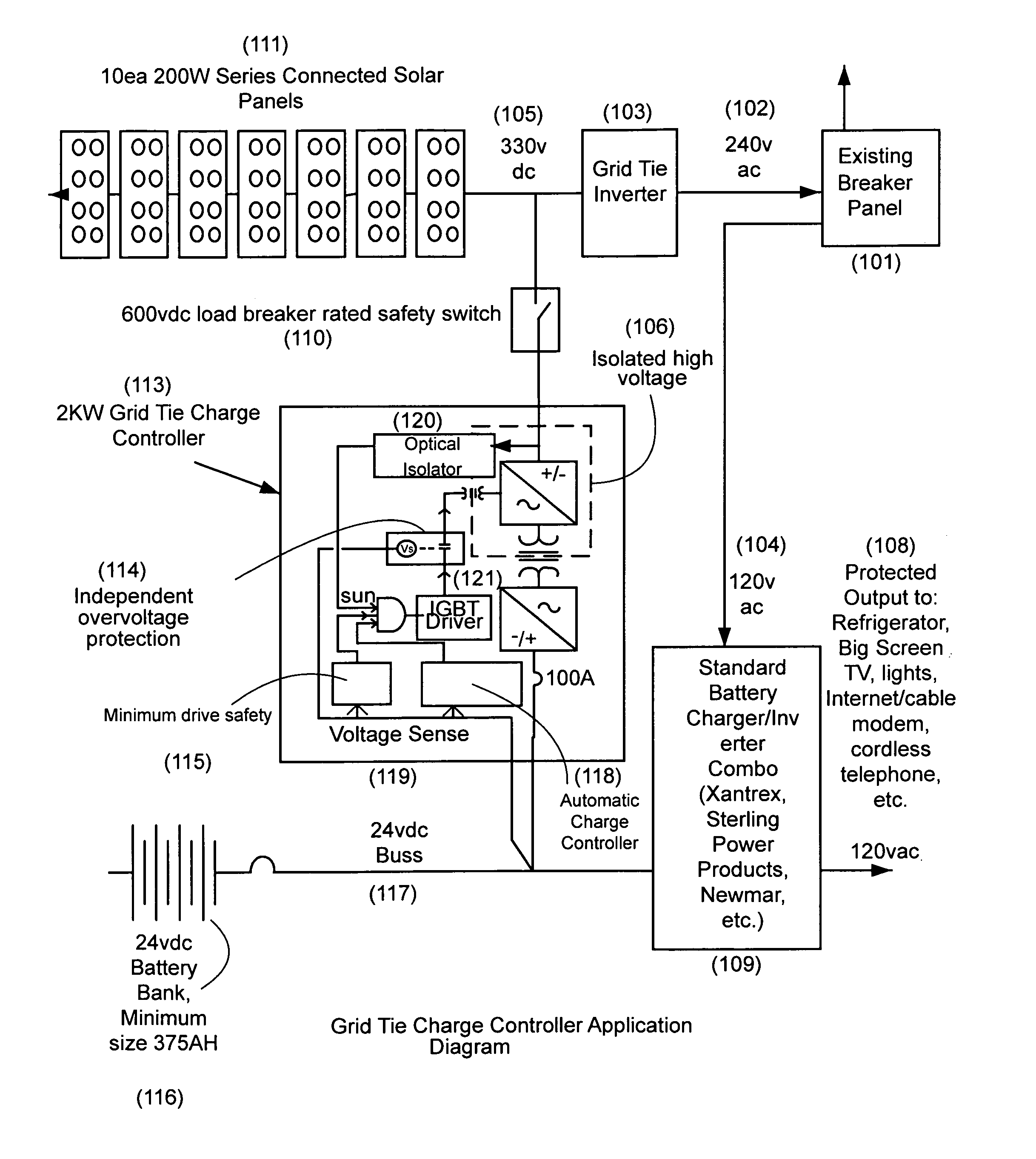
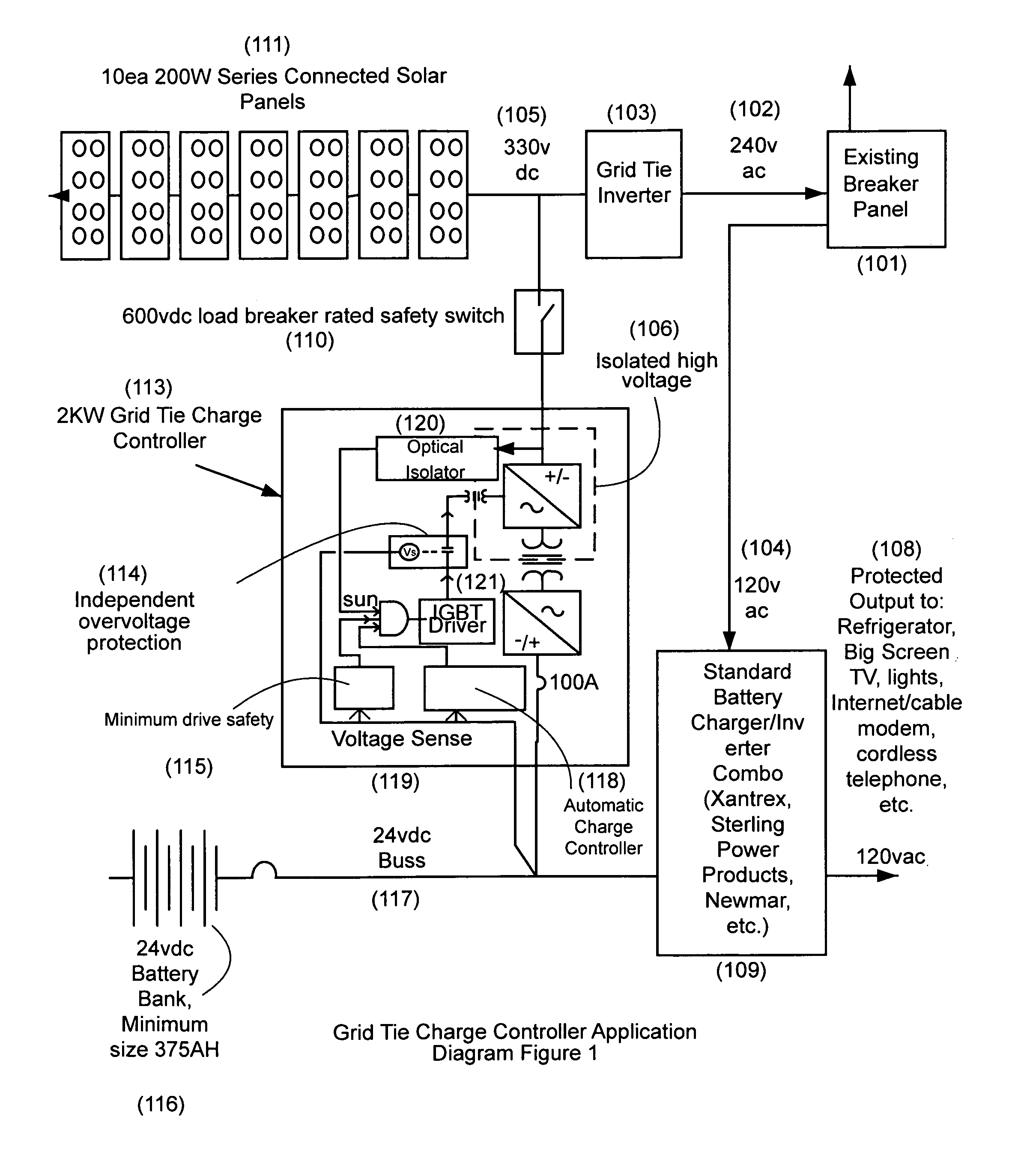
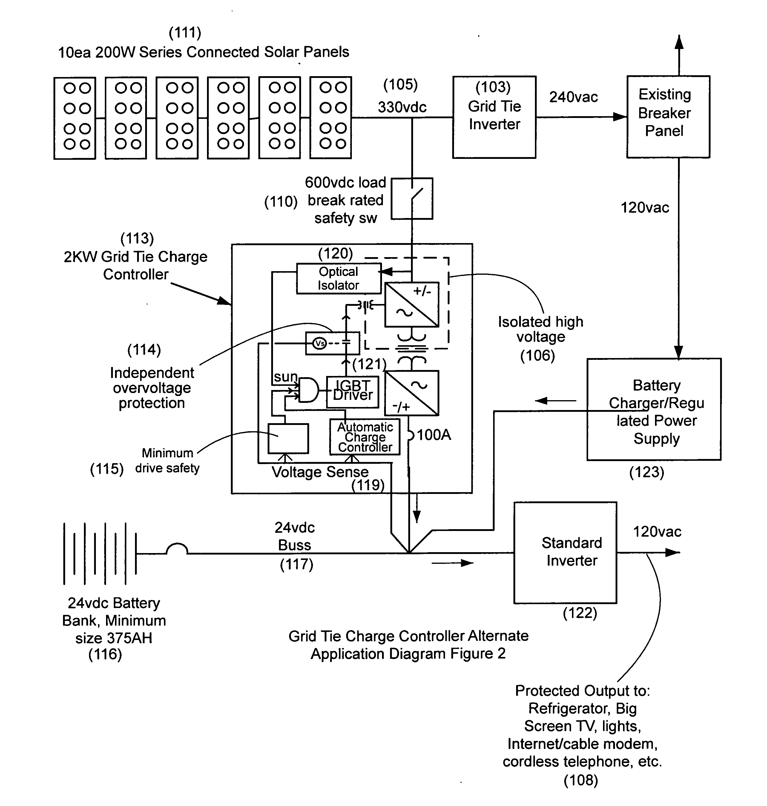
[0085]A grid tie charge controller system for an existing high-voltage photovoltaic array has a grid tied charge controller connecting in parallel between an existing high voltage photovoltaic array and an existing high voltage gird tie inverter. The present invention grid tie charge controller system 113 ties in between the 330 V DC side 105 and the 24 V DC bus 117 so that it completely bypasses the grid tie inverter. It can be used along with a standard charge controller, or without if a standard charge controller is absent. The grid tie charge controller is configured to retrofit “tap in” to an existing grid tie photovoltaic system to draw off power to charge storage batteries; (See FIG. 1&FIG. 2. Application Diagrams) The grid tie charge controller has a transformer that transforms the relatively high voltage (200-500 vdc) of a typical grid tie solar system down to low voltage, high current, 12 / 24 v battery bank typically used in an “off grid” type systems; and (See FIG. 3. Bloc...


PUM


Abstract

A system extracts power from a typical high voltage (200-500 vdc) grid tie solar system and deliver it to a low voltage (12-24 vdc) battery bank. This product parallel connects in between an existing grid tie solar array, and an existing grid tie inverter, transforming the voltage down, and acting as a charge controller, engaging and disengaging as necessary to keep the low voltage battery bank at a high state of charge. This system enables the grid tie PV array to have a second use as the energy source for a low DC voltage off grid system. This system, when combined with standard low DC voltage grid inter-active off grid inverter / charger, and a battery bank, forms a complete off grid system, while allowing the host grid tie system to function normally when the grid is on.

Description

[0001]The present invention is a non-provisional of and claims priority from provisional application 62 / 027,555 filed Jul. 22, 2014 by same inventor F. H. (Rick) Smith, of Bakersfield, Calif. entitled Grid Tie Charge Controller, the disclosure of which is incorporated herein by reference.FIELD OF THE INVENTION[0002]The present invention is in the field of grid tied charge controllers, more specifically a method for making a high voltage photovoltaic array work for both on and off grid applications.DISCUSSION OF RELATED ART[0003]The evolution of on grid and off grid photovoltaic systems has naturally resulted in differing architectures between on grid and off grid systems. Since power grids have historically been very reliable, on grid systems have focused on efficiency, and have therefore been generally designed to operate at high voltages in hopes of minimizing both IR losses, transistor junction losses, and in some cases transformer losses, while not giving consideration to adding...

Claims


Application Information

Patent Timeline
Patent Type & Authority Applications(United States)
IPC IPC(8): H02J7/35
CPCH02J7/35H02J2300/26H02J2300/24H02J3/381Y02B10/10Y02E10/56H02J3/46
Inventor SMITH, RICK
Owner SMITH RICK
Why Eureka
Try Eureka