Drive device assembled by an interference fit

a technology of interference fit and drive device, which is applied in the direction of magnetic circuit rotating parts, propulsion by batteries/cells, and shape/form/construction of magnetic circuits, etc. it can solve the problems of noise of motor and/or torque pulsation, insufficient heat dissipation capacity of heat sink insufficient heat dissipation capacity of heat sink to dissipate heat toward the motor case, etc., to improve the heat dissip

Inactive Publication Date: 2016-02-04
DENSO CORP
View PDF0 Cites 29 Cited by
  • Summary
  • Abstract
  • Description
  • Claims
  • Application Information

AI Technical Summary

Benefits of technology

[0015]The drive device of the present disclosure may have improved assembly accuracy, i.e., coaxiality, based on the inference fit between the fitting outer wall of one of the heat sink and the bottom plate and the fitting inner wall of the frame. Based on the assumption that the fitting outer wall of the second concave part are coaxially positioned in one body, i.e., as a single component, and that the fitting outer wall of the bottom plate and the first concave part is coaxially positioned in one body, i.e., also as a single component, the second bearing in the second concave part and the first bearing in the first concave part are coaxially positioned, or accurately aligned with each other, by the inference fit described above, thereby enabling the coaxial installation of the shaft by the two bearings on two axial, opposing ends in the motor section of the drive device and guaranteeing the perpendicular setting of the shaft against the bottom plate. Therefore, the tilt of the shaft leading to the motor noise or the pulsation of the motor is appropriately prevented.
[0016]The inference fit further contributes to the high heat conductivity between the heat sink and the frame and between the frame and the bottom plate, thereby improving the heat dissipation capacity of the drive device, i.e., from the electric element of the controller section to a bottom-plate bearing object which has the bottom plate attached thereto, v...

Problems solved by technology

However, in such a fix method, a size of a contact surface between the heat sink and the motor case is not sufficiently reserved, thereby making a heat dissipation capacity to dissipate heat from the heat sink toward the motor case insufficient.
However, when the heat sink is fixed onto the motor case with the bending of the claw or with the screwing of the substrate, accuracy of such assembly will not be guaranteed, in terms of the coaxiality between the two bearings, i.e., betw...

Method used


Image

  • Drive device assembled by an interference fit
  • Drive device assembled by an interference fit
  • Drive device assembled by an interference fit

Examples


first embodiment

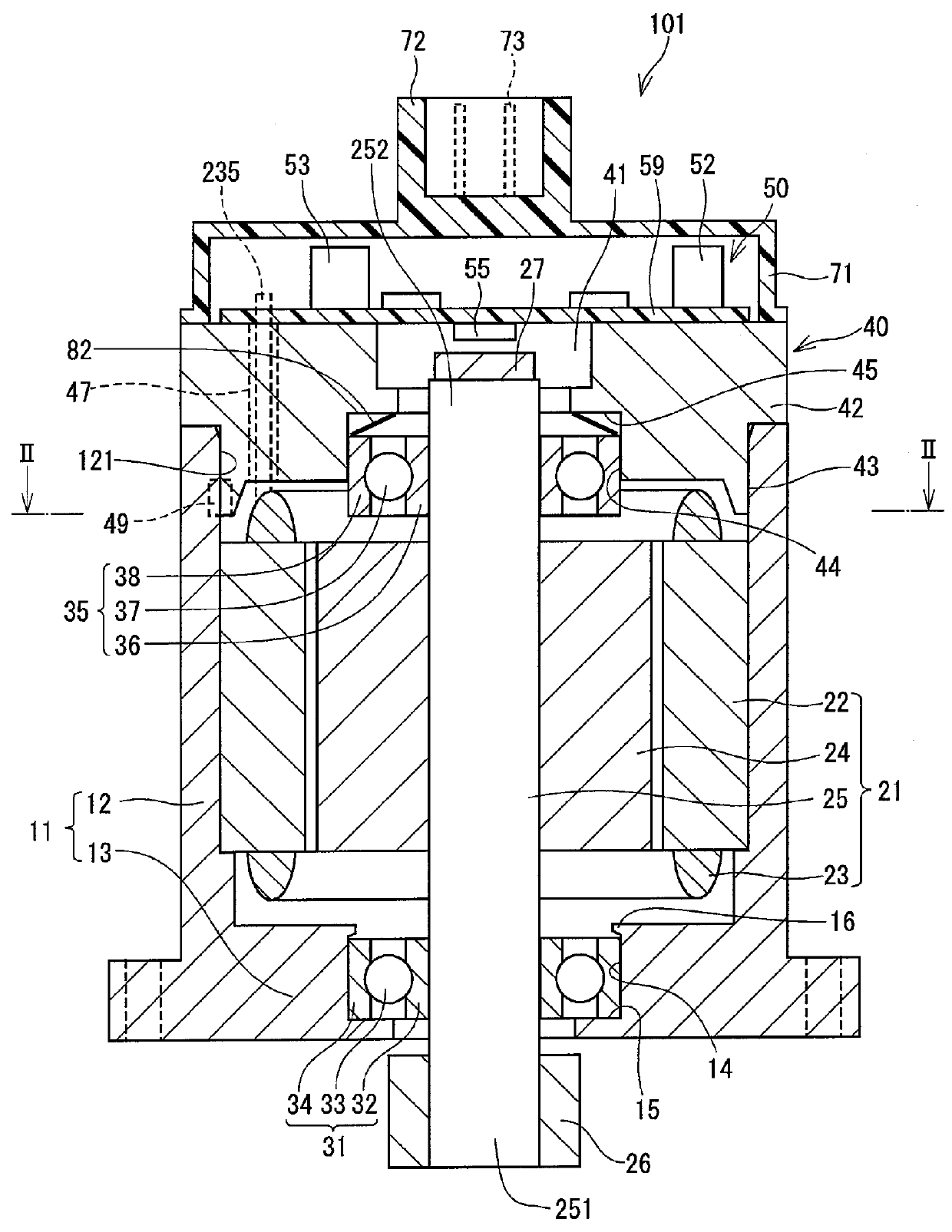
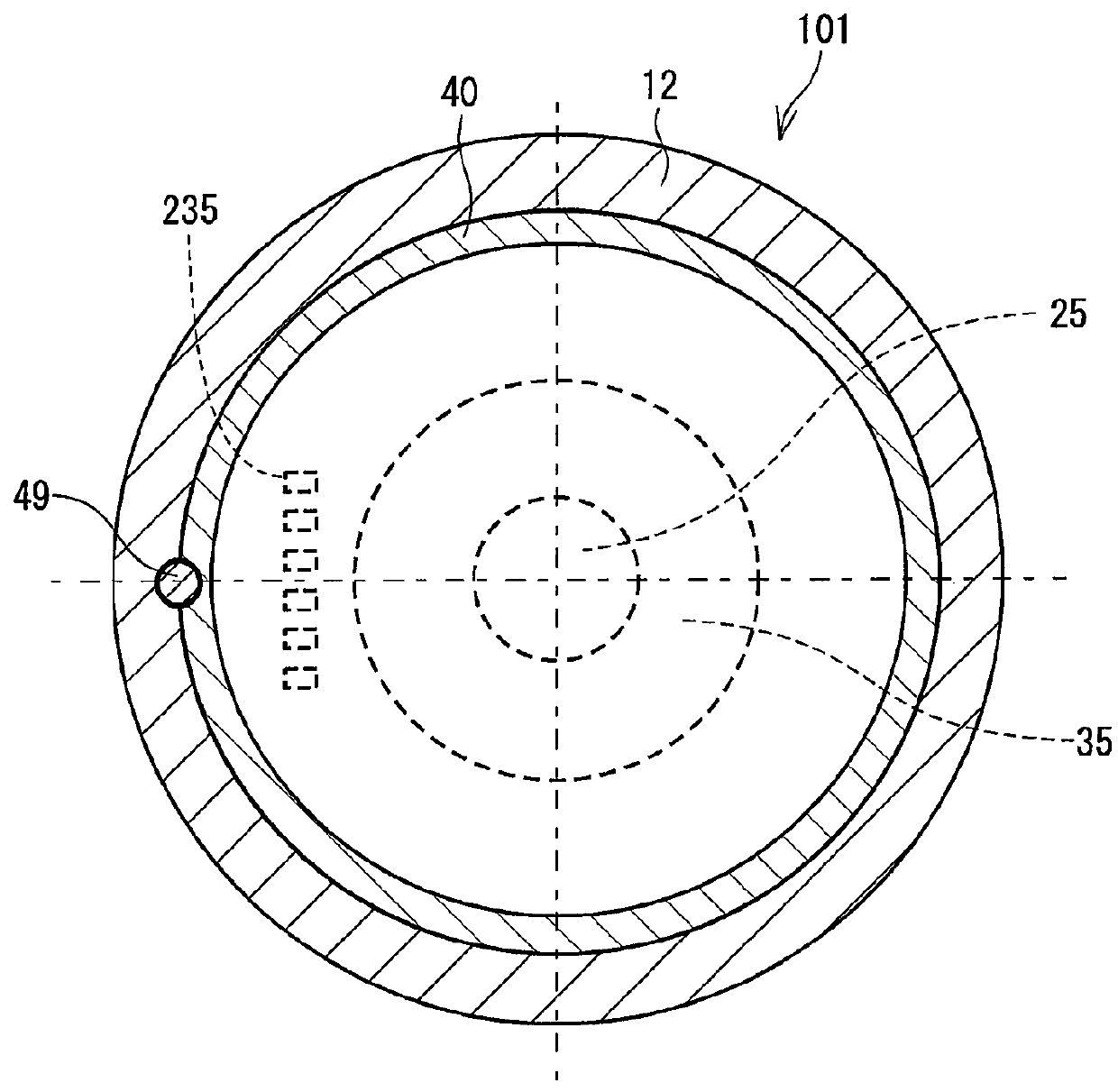
[0030]The drive device in the first embodiment of the present disclosure is described with reference to FIGS. 1-5.

[0031]A drive device 101 of the present embodiment is an actuator which is a one-body combination of a motor part and a controller part, among which the motor part generates a steering assist torque in an electric power steering device of a vehicle, and the controller part controls a power supply of the motor part.

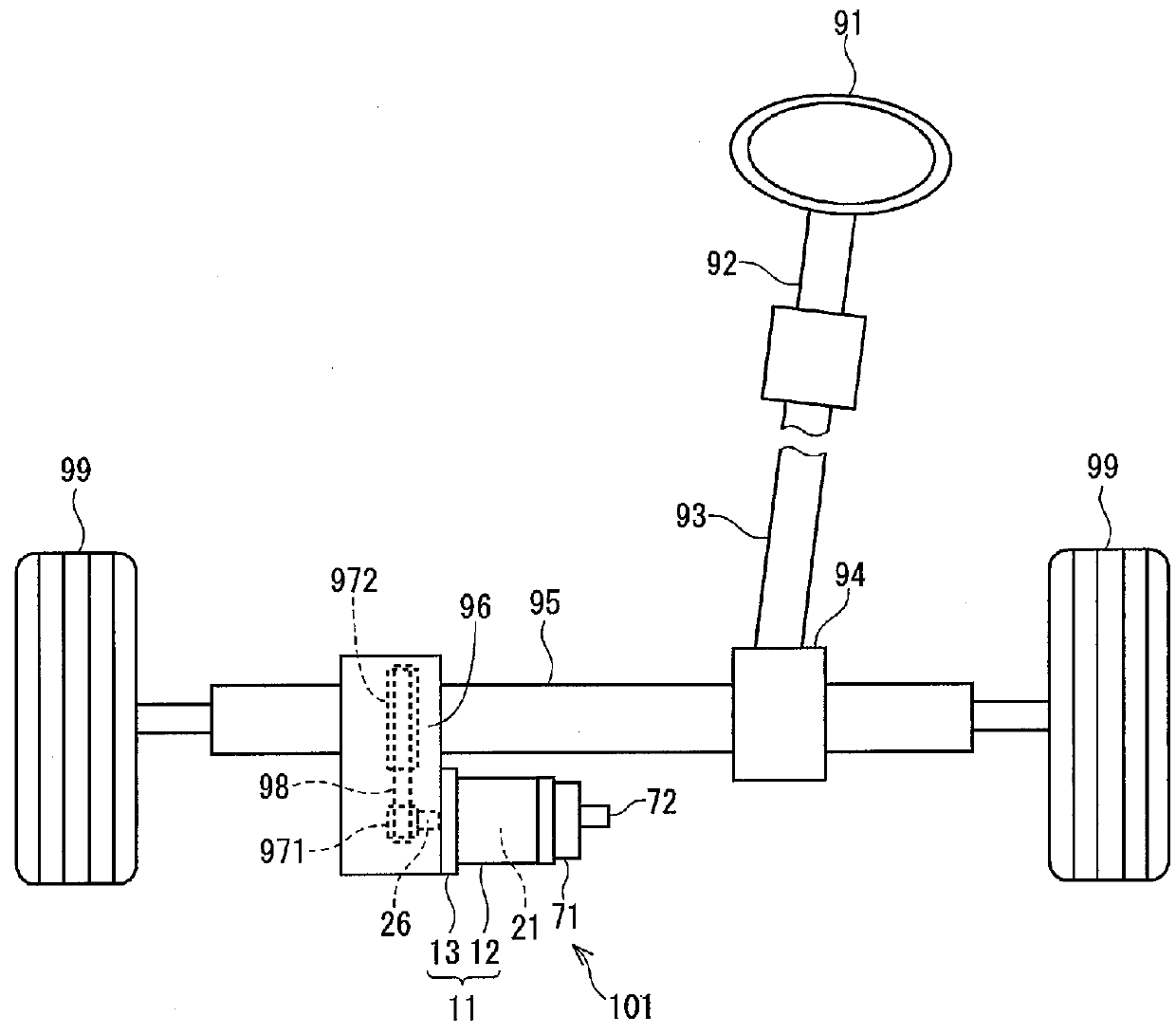
[0032]First, with reference to FIG. 3, the configuration of an electric power steering device 90 is described, to which the drive device 101 of the first embodiment and of the other embodiments is used.

[0033]The steering torque by a driver is transmitted from a steering wheel 91 to an intermediate shaft 93 via a steering shaft 92, and a rotational movement is turned into a straight-line, translational movement of a rack shaft 95 in a rack and pinion mechanism 94. Then, according to an amount of the straight-line movement of the rack shaft 95, a pair of wheels 9...

second embodiment

[0096]The drive device in the second embodiment of the present disclosure is shown in FIG. 6.

[0097]A drive device 102 in the second embodiment is different from the drive device 101 in the first embodiment in that a seal member 83 is inserted in a slot 48 that is formed on the fitting outer wall 43 of the heat sink 40. The seal member 83 is an O ring made of rubber, for example, and the seal member 83 seals a fluid (i.e., gas or liquid) at a position between the fitting outer wall 43 and the fitting inner wall 121 of the frame 12.

[0098]Since the rack-mount type electric power steering device 90 suffers from a rain water splashing from a road surface, a rain water dripping along the rack shaft 95, a leaking radiator fluid and washer fluid, which may intrude into the drive device 102, a water-proof character of the drive device 102 is on high demand. Therefore, the seal member 83 is effectively used in the drive device 102 in such a situation for providing water-proof character.

[0099]...

third embodiment

[0100]The drive device in the third embodiment of the present disclosure is described in the following with reference to FIG. 7 and FIG. 8.

[0101]According to the third embodiment, the configuration of the frame and the bottom plate, and an assembly order of the drive device differ from the first embodiment.

[0102]The drive device 103 of the third embodiment has a cylinder shape frame 17 and a bottom plate 18 provided in two separate pieces. The bottom plate 18 closes an opening of the frame 17 on an output shaft 26 side. The frame 17 has, on one end of the frame 17, a fitting inner wall 171 that is combinable with the fitting outer wall 43 of the heat sink 40 by fitting. On the other end of the frame 17, a fitting inner wall 172 that is combinable with a fitting outer wall 19 of the bottom plate 18 is provided.

[0103]Here, just like the first embodiment, the outer dimension of the fitting outer wall 19 is set to a suitable size against to the inner diameter dimension of the fitting in...


PUM


Abstract

A drive device is assembled with a fitting outer wall of a heat sink and a fitting inner wall of a frame combined by an interference fit. The drive device allows for a sufficient assembly accuracy of coaxiality, and may prevent a pulsation of motor torque and a vibration sound caused by a tilt of a shaft. Further, heat conductivity at a contacting portion is improved for heat dissipation from an electronic element in a controller section via the heat sink, the frame, and a bottom plate.

Description

CROSS REFERENCE TO RELATED APPLICATION[0001]The present application is based on and claims the benefit of priority of Japanese Patent Application No. 2014-156478, filed on Jul. 31, 2014, the disclosure of which is incorporated herein by reference.TECHNICAL FIELD[0002]The present disclosure generally relates to a drive device that has a motor section and a controller assembled by an interference fit along an axial direction.BACKGROUND INFORMATION[0003]Conventionally, the drive device has a motor section and a controller, which controls a power supply for a winding of the motor section, and the controller is assembled along an axis direction, i.e., along a shaft direction, of the motor to complete the drive device. For example, the drive device disclosed in a patent document, Japanese Patent Laid-Open No. 2011-228379 (Patent document 1) has a motor section that accommodates a stator and a rotor and a heat sink combined along the axis direction to have one integrated body, in which a c...

Claims


Application Information

Patent Timeline
IPC IPC(8): H02K9/22B62D5/04H02K1/16H02K5/15H02K7/00H02K7/08H02K7/14H02K11/00
CPCH02K9/22H02K1/16H02K7/003B62D5/0421H02K7/14H02K5/15H02K11/0073H02K7/083H02K11/33B62D5/0406B60L2210/40B60L2270/145B60L50/60Y02T10/64Y02T10/72Y02T10/70H02K9/227
Inventor HAYASHI, JIROU
Owner DENSO CORP
Why Eureka
Try Eureka