

Microchannel Apparatus and Methods of Conducting Unit Operations With Disrupted Flow
a microchannel apparatus and flow technology, applied in indirect heat exchangers, lighting and heating apparatuses, laminated elements, etc., can solve the problems of large momentum effects, flow mal-distribution, and drop of manifold pressure, and achieve the effect of improving heat transfer coefficient and maximizing heat transfer
- Summary
- Abstract
- Description
- Claims
- Application Information
AI Technical Summary
Benefits of technology
Problems solved by technology
Method used
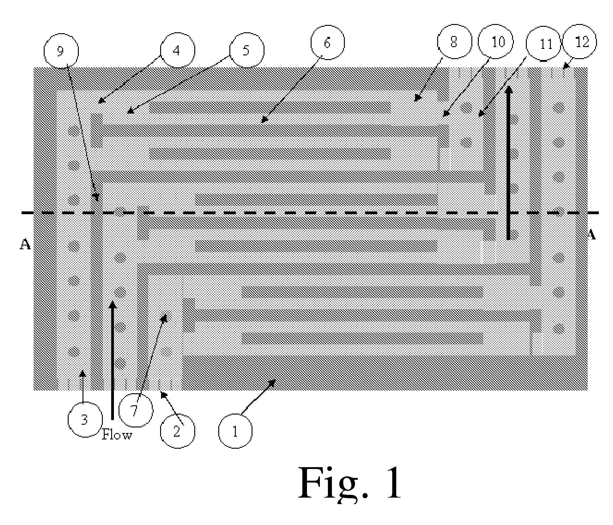
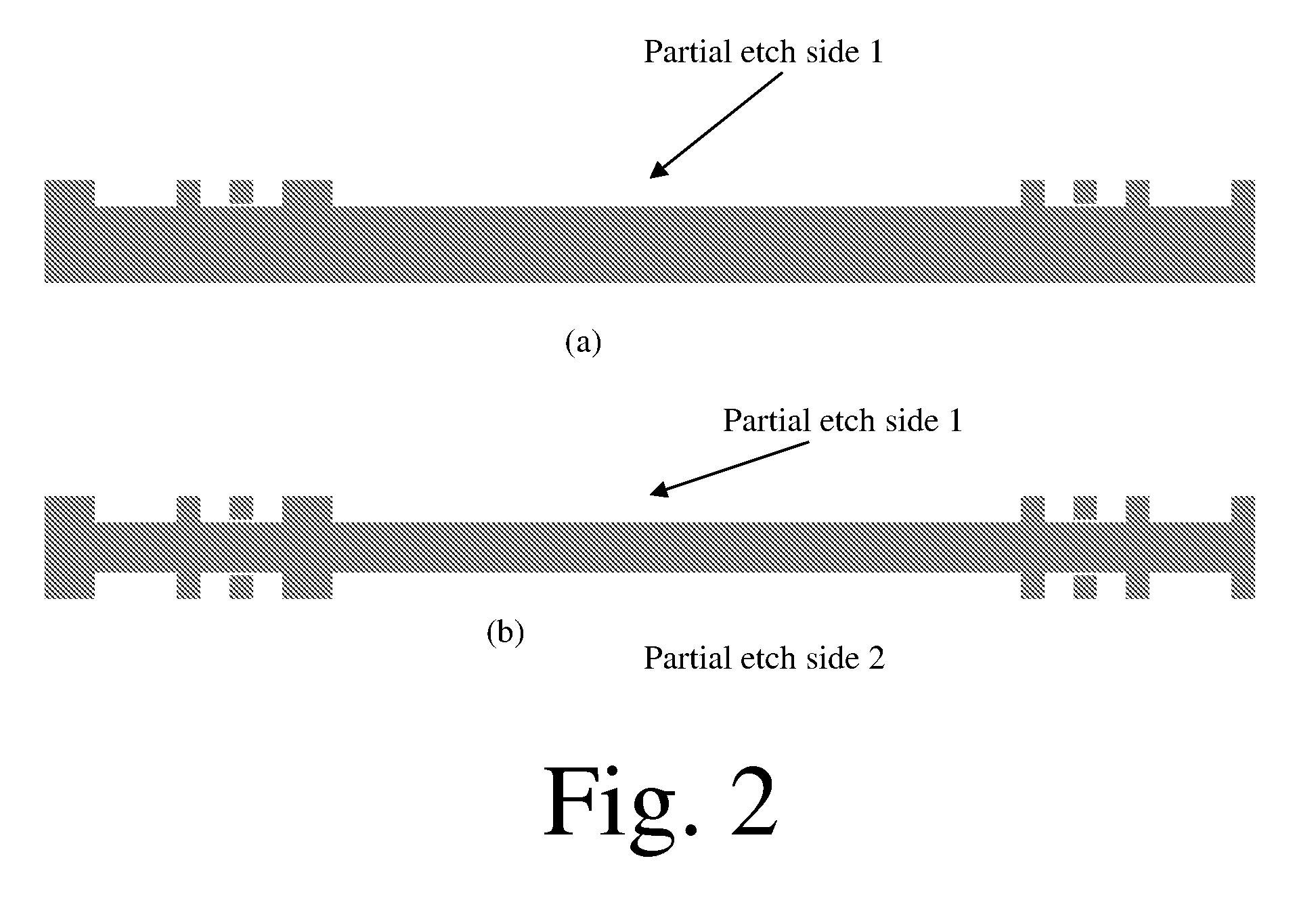
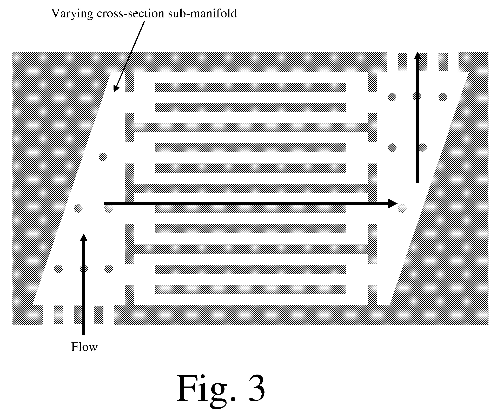
Image

Examples
example
Calculated Comparison of Two Heat Exchanger Designs
[0095]Two heat exchanger designs were compared: One with large microchannels and other with smaller microchannels. The heat exchanger was a two stream counter-current heat exchanger as shown in the FIG. 10. Table 1 lists the inlet conditions and outlet requirements for the two streams.
TABLE 1Inlet conditions and outlet requirements for heat exchangerConditionStream AStream BMass flow rate (kg / hr)202604 kg / hr202604 kg / hrInlet temperature (° C.)374°C.481°C.Desired outlet temperature (° C.)472°C.385°C.Outlet pressure (psig)349.8 psig323.3 psigAllowable pressure drop (psi)4.0 psi3.0 psi
The composition of Stream A and Stream B are summarized below in Table 2.
TABLE 2Molar composition of Stream A and Stream BMolar Composition (%)ComponentStream AStream BWater57.01%69.20%Nitrogen 0.78% 0.84%Hydrogen10.29% 0.76%Carbon-monoxide 0.11% 0.02%Carbon-dioxide 3.97% 0.31%Methane27.83%24.97%Ethane 0.00% 2.03%Propane 0.00% 0.82%n-butane 0.00% 0.47%n-p...
PUM
| Property | Measurement | Unit |
|---|---|---|
| length | aaaaa | aaaaa |
| Reynold's number | aaaaa | aaaaa |
| inner diameter | aaaaa | aaaaa |
Abstract
Description
Claims
Application Information