Composite panel for green building system

Inactive Publication Date: 2016-02-25
PERFECT SOURCING COMPANY
View PDF34 Cites 1 Cited by
  • Summary
  • Abstract
  • Description
  • Claims
  • Application Information

AI Technical Summary

Benefits of technology

[0040]4. Since the honeycomb structure and its filler is covered by face plates or the load-bearing layer, the filler is prevented from decomposition or pulverization. Green building systems that adopt the composite panels require less maintenance, thus saving cost.
[0041]5. The composite panels provide more design freedom to designers for having 3-D impression because the composite panels are thicker than usual concrete plates.
[0042]6. Since the composite panels provide good thermal insulation, water or moisture condensation is prevented from occurring inside the green building when

Problems solved by technology

In other words, the honeycomb structure may be easily crushed or destroyed by applying load to its lateral axis.
Since the

Method used


Image

  • Composite panel for green building system
  • Composite panel for green building system
  • Composite panel for green building system

Examples


Example

[0051]FIGS. 1-2 relate to a first embodiment of the present application. The first embodiment has parts or method steps that are similar or identical to other embodiments of the application. Description of the similar or identical parts is hereby included by reference wherever appropriate.

[0052]In particular, FIG. 1 illustrates a first composite panel 20 that is cut off and exposed for showing its internal structure. The first composite panel 20 is vertically inserted into a concrete foundation 22 that is horizontally laid. In other words, the first composite panel 20 provides a portion of a load-bearing wall 24 (bearing wall) of a building 26, which is situated and supported by the concrete foundation 22. The concrete foundation 22 is also known as shallow foundation for a house or a deep foundation for a skyscraper.

[0053]The first composite panel 20 comprises many layers of materials or strata of various thicknesses, which are sequentially attached to each other. According to FIG....

Example

[0071]FIG. 3 relates to a second embodiment of the present application. Particularly, FIG. 3 depicts parts or method steps that are similar or identical to those of one or more other embodiments. Description of the identical or similar parts or method steps is therefore incorporated by reference wherever appropriate.

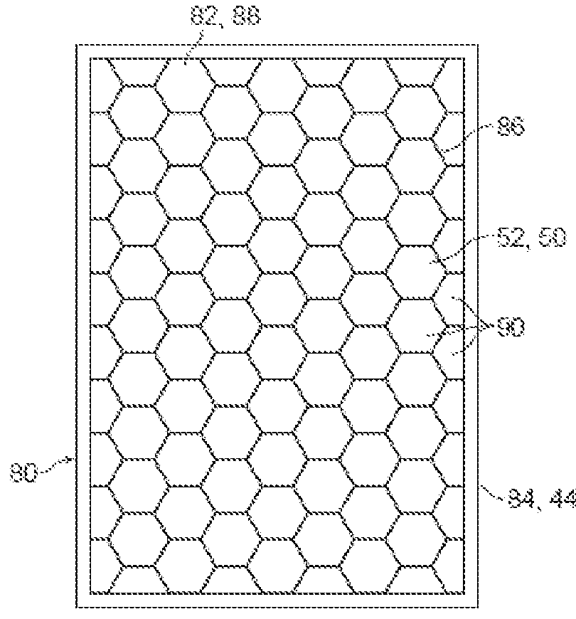
[0072]In detail, FIG. 3 illustrates a second composite panel 80, which is also known as composite sandwich panel. The second composite panel 80 is exposed on one broad planar surface 82, showing a concrete frame 84, a paper honeycomb core 86 and polyurethane foam 50 as its filler 52. The broad planar surface 82 and its opposite side (not visible) 88 are graphite skin or face sheet. The graphite skin covers edges of the concrete frame 84, whilst the graphite skin may be replaced by fibre, aluminium or epoxy skin. The concrete frame 84 is homopolymer polypropylene fibre reinforced concrete that is created by a mould surrounding the paper honeycomb web. The concrete frame 8...

Example

[0076]FIG. 4 relates to a third embodiment of the present application. Particularly, FIG. 4 depicts parts or method steps that are similar or identical to those of one or more other embodiments. Description of the identical or similar parts or method steps is therefore incorporated by reference wherever appropriate.

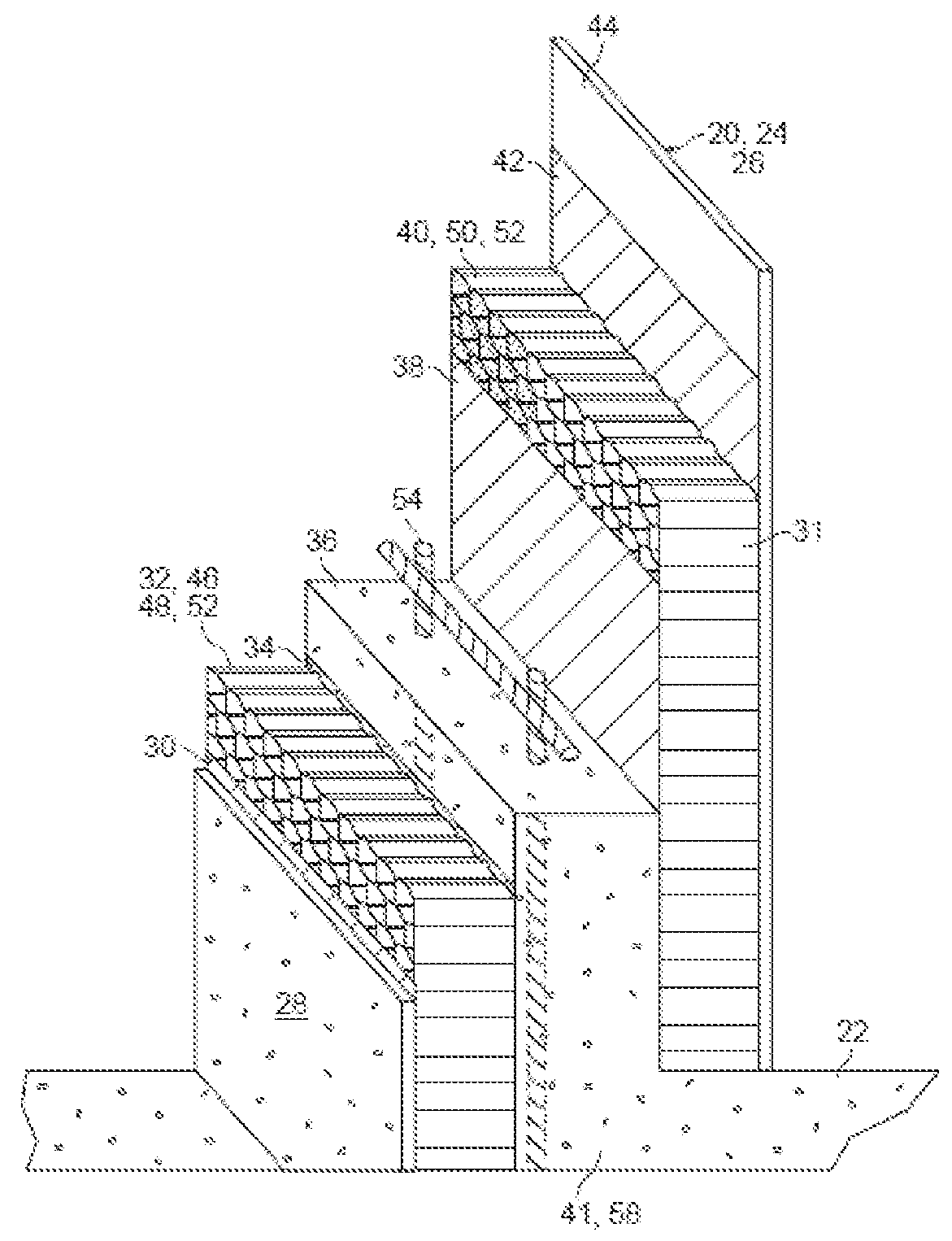
[0077]In detail, FIG. 4 illustrates a third composite panel 120 that comprises a concrete baseplate 28, a slab adhesive layer 38, an aluminium web 32, a plate adhesive layer 42 and a transparent face sheet 122, from top to bottom sequentially. The third composite panel 120 has a concrete frame 84 of rectangular shape (not shown), which surrounds peripheral edges of the aluminium web 32. The concrete frame 84 also joins the concrete baseplate 28 and the transparent face sheet 122 at its opposite sides in forming the monolithic third composite panel 120. Particularly, the transparent face sheet 122 is made of Perspex™ material (acrylic glass, Lucite, acrylite), which is als...


PUM

PropertyMeasurementUnit
Structureaaaaaaaaaa
Transparencyaaaaaaaaaa
Reflectionaaaaaaaaaa

Abstract

Composite panel for building construction comprises a first layer of honeycomb structure, and a load-bearing layer attached to the first layer of honeycomb structure contiguously or at distance for carrying external load of the composite panel in a lateral direction of the honeycomb structure.

Description

CROSS REFERENCE TO RELATED APPLICATIONS[0001]This application claims priority of Singapore application No. 10201405027S, filed on Aug. 19, 2014, the entire contents of which are all hereby incorporated by reference.BACKGROUND[0002]1. Technical Field[0003]The present application relates to one or more composite panels for green building system. The application also relates methods of making, separating, joining, scraping, modifying, maintaining, recycling and using the one or more composite panels for green building system.[0004]2. Related Art[0005]Composite panels (also known as composition materials, composite materials or composites) are construction materials made from two or more constituent materials with different physical or chemical properties respectively. The individual constituent materials typically remain separate and distinct from each other within a finished structure of the composite materials. The composite panels become attractive to building industry because they ...

Claims


Application Information

Patent Timeline
IPC IPC(8): B32B13/04B32B3/12E04B2/00E04C2/04E04C2/08E04C2/20
CPCB32B3/12B32B13/04E04C2/04E04C2/08B32B2607/00E04C2/46B32B2305/024B32B2307/54B32B2419/00E04C2/20B32B7/12B32B13/02B32B13/06B32B13/12B32B15/20B32B27/20B32B2262/101B32B2307/306B32B2307/3065B32B2307/412B32B2307/416B32B2307/712B32B2307/714B32B2307/7145B32B2307/7265B32B2307/752E04C2/365
Inventor HO, HOK, CHEUNG
Owner PERFECT SOURCING COMPANY
Why Eureka
Try Eureka