Apparatus and method for measuring the concentration of trace gases by scar spectroscopy

a technology of scar spectroscopy and apparatus, which is applied in the direction of material analysis, instruments, spectral investigation, etc., can solve the problems of increasing radiation intensity in the cavity, affecting the accuracy of the signal obtained, and affecting the overall dimensions of the same equipment. , to achieve the effect of reducing the length of spatial correlation of the beam and increasing the signal accuracy

Active Publication Date: 2016-02-25
CONSIGLIO NAT DELLE RICERCHE
View PDF3 Cites 14 Cited by
  • Summary
  • Abstract
  • Description
  • Claims
  • Application Information

AI Technical Summary

Benefits of technology

[0067]The presence of the diffuser allows increasing the accuracy of the signal obtained.
[0068]The diffuser element at least partly evens the signal that reaches the surface of the photodetector, for example preventing the signal from mainly reaching some points of the same, and at the same time reduces the length of spatial correlation of the beam on the illuminated surface of the photodetector, randomly varying the interference fringes that may form on the surface of the same, on a length scale shorter than that of the spatial heterogeneity of its response.
[0069]In this way, even if the alignment between cavity-focusing means and photodetector fluctuates, the effect on the photodetector is made “even”.
[0070]Additionally, the diffuser element decreases the power of the signal that is focused on the photodetector itself: the intensity that must be used by the laser beam is high in order to achieve saturation of the gas in the cavity, however such a power can be detrimental in case a signal of this type reaches the detector itself.
[0071]The diffuser element ensures illumination on the photodetector as uniform as possible and independent of the spatial fluctuations of the beam transmitted by the cavity.

Problems solved by technology

However, the costs related to AMS equipment are relevant, in the order of millions of euros, and the overall dimensions of the same equipment is substantial, with high operating voltages.
When the radiation emitted by the laser is in resonance with a cavity mode, the radiation intensity increases in the cavity due to constructive interference phenomena.
If a gas or a mixture of gases that absorb light is placed inside the cavity, the intensity of photons trapped decreases by a fixed percentage along each path inside the cavity due to the scattering and absorption by the medium in the cavity and due to reflectivity losses.

Method used


Image

  • Apparatus and method for measuring the concentration of trace gases by scar spectroscopy
  • Apparatus and method for measuring the concentration of trace gases by scar spectroscopy
  • Apparatus and method for measuring the concentration of trace gases by scar spectroscopy

Examples


Embodiment Construction

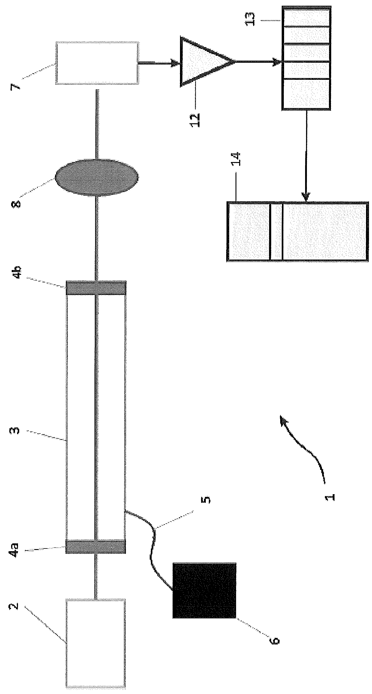
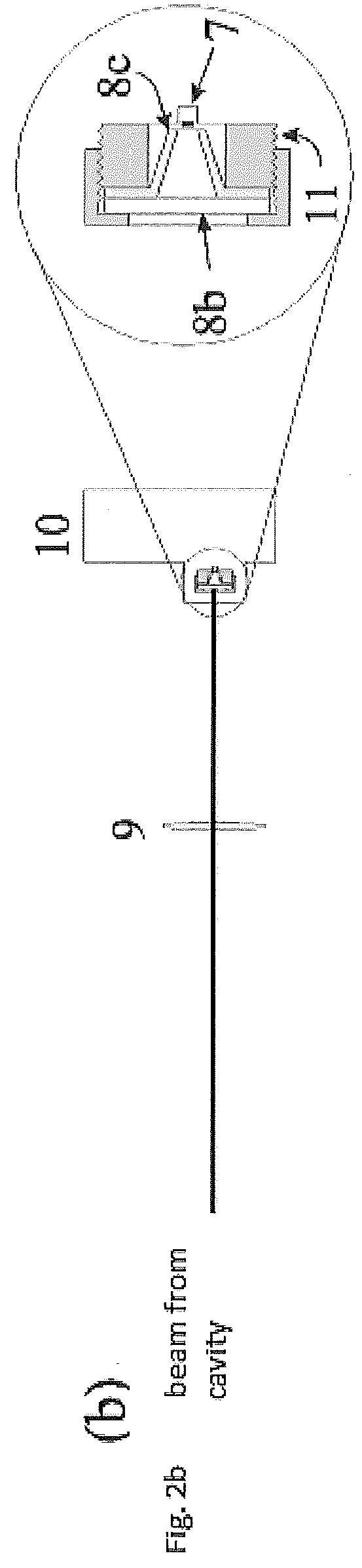
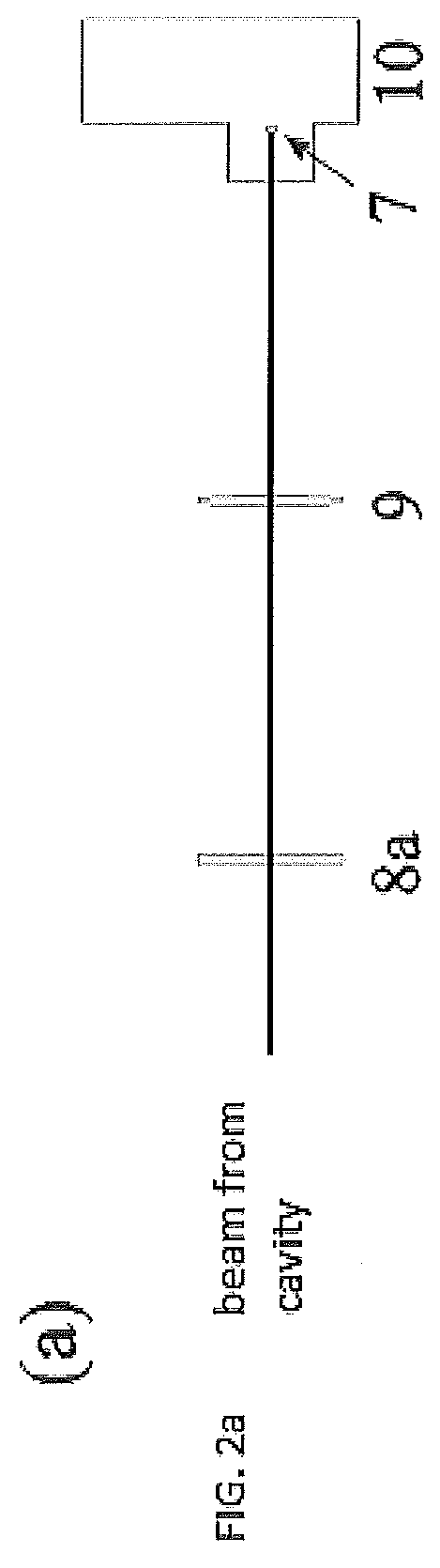
[0102]With initial reference to FIG. 1, reference numeral 1 indicates an apparatus for SCAR spectroscopy including a laser source 2, for example a continuous wave (CW) coherent laser source generated by a frequency difference tunable over a predetermined range.

[0103]Preferably, the radiation emitted by laser source 2 has a wavelength in the mid-infrared, however other wavelengths may be used. The mid-infrared has the advantage of having the strongest molecular absorption.

[0104]The type of laser source 2 used in the present invention is for example described in the article written by Galli et al., Opt. Lett. 35, 3616 (2010). Other types of laser sources may be used, provided that the intensity of radiation I inside the cavity is much greater than the intensity of saturation Is of the molecular transition to be detected, i.e. I>>Is.

[0105]For example, in a range of wavelengths of 4-5 μm, for the transitions of CO2, which have an Einstein coefficient A of about 200 s−1, at a pressure of...


PUM

PropertyMeasurementUnit
reflectivityaaaaaaaaaa
pressureaaaaaaaaaa
pressureaaaaaaaaaa

Abstract

The present invention relates to a ring-down spectrometry apparatus in absorption saturation condition, for measuring the concentration of a gas through a measurement of the spectrum of a molecular transition of said gas. The apparatus includes a laser source, an adjuster for varying the wavelength of said radiation emitted by said laser, and a resonant cavity. A photodetector is adapted to detect an electromagnetic radiation beam and is adapted to generate a decay signal. An electronic circuit receives the signal from the photodetector and is adapted to convert it to a processor. A processor is adapted to receive said decay signal from the photodetector and perform interpolation to obtain a concentration of said gas.

Description

CROSS REFERENCE TO RELATED APPLICATIONS[0001]This application is a 371 of International Application No. PCT / IB2014 / 060739 filed Apr. 15, 2014, which claims the benefit of Italian Application No. PD2013A000095, which was filed on Apr. 15, 2013, and are incorporated herein by reference as if fully set forth.FIELD OF INVENTION[0002]The present invention relates to an apparatus employing an optical detection technique called saturated-absorption cavity ring-down spectroscopy (which hereafter will be referred to as SCAR for brevity) for detecting the concentration of trace gases, in particular for trace gases present in part per trillion (10−12), for example for the detection of radiocarbon at concentration levels much lower than those present as natural abundance.BACKGROUND[0003]The so-called method of 14C (carbon-14 or radiocarbon), is a radiometric dating method based on the measurement of relative abundances of carbon isotopes. The method of 14C allows dating organic materials (bone,...

Claims


Application Information

Patent Timeline
Patent Type & Authority Applications(United States)
IPC IPC(8): G01J3/42G01J3/02G01N21/27G01N21/3504
CPCG01J3/42G01J3/0205G01N2201/06113G01N21/274G01N2201/068G01N21/3504G01N21/031G01N21/39
Inventor GIUSFREDI, GIOVANNIGALLI, IACOPOPASTOR, PABLO CANCIOMAZZOTTI, DAVIDEDE NATALE, PAOLO
Owner CONSIGLIO NAT DELLE RICERCHE
Why Eureka
Try Eureka