Pressure Vessels, Design and Method of Manufacturing Using Additive Printing

a technology of additive printing and pressure vessels, applied in the field of pressure vessels, can solve the problems of not considering the possibility of pressure vessels, and achieve the effects of improving construction, increasing pressure differentials, and increasing production efficiency

Inactive Publication Date: 2016-03-03
KOTLIAR IGOR K
View PDF5 Cites 67 Cited by
  • Summary
  • Abstract
  • Description
  • Claims
  • Application Information

AI Technical Summary

Benefits of technology

[0042]The inventive method utilizes Additive Manufacturing and / or 3D Printing technology that allows the creation of a unique design of a pressure vessel, cylinder or other container under positive or negative pressure, using an internal supportive structure that allows for the reduction of pressure applied to the walls of the Pressure Vessel and / or the application of counterbalancing pressures to those walls. This allows for the fabrication of such vessels or containers that are lighter and stronger that current industry product, using less material and without any waste.
[0046]The present invention provides a new approach to the design and manufacturing method of a Pressure Vessel, which allows for making it lighter, stronger and capable of withstanding much greater pressure differentials (whether it is the pressure within the vessel which is greater, or the pressure outside the vessel which is greater) than heretofore known. In this context, a “much greater” pressure differential is one which is at least 5 times, and, more preferably, at least 10 times greater than known pressure differentials for vessels made of similar materials and with similar construction. For example, a currently known container for holding liquefied natural gas made of reinforced steel may be capable of withstanding a pressure differential of 300 bar, while a vessel made in accordance with the inventive method and design may be capable of withstanding a pressure differential of 10,000 bar. It will also be appreciated by one of ordinary skill in the art that, simply because a vessel may be capable of withstanding such a great pressure differential does not require that the vessel be subjected to any pressure differential whatsoever. Again, by way of example only, essentially every vessel is manufactured in a zero-differential environment, and, even after construction, may not be subjected to a differential pressure environment for some time, if ever. Some vessels made in accordance with the invention may be used for containing fluids at a zero-differential pressure environment, such as holding gasoline in a passenger vehicle. However, these vessels may be capable of withstanding higher pressure differentials due to their construction compared with known fuel tanks, and can therefore be made lighter due to their improved construction.
[0047]It is a further object of the invention to provide a vessel for use in vehicles which run on stored hydrogen, methane or other gases that would be able to safely accommodate much larger volumes of fuel by increasing storage and / or pressure.

Problems solved by technology

Furthermore, no one thought about the possibility of making pressure vessels using a 3D printing process, which allows for the production of a whole vessel in one process and without use of human intervention and, most importantly, without waste materials.

Method used


Image

  • Pressure Vessels, Design and Method of Manufacturing Using Additive Printing
  • Pressure Vessels, Design and Method of Manufacturing Using Additive Printing
  • Pressure Vessels, Design and Method of Manufacturing Using Additive Printing

Examples


embodiment 10

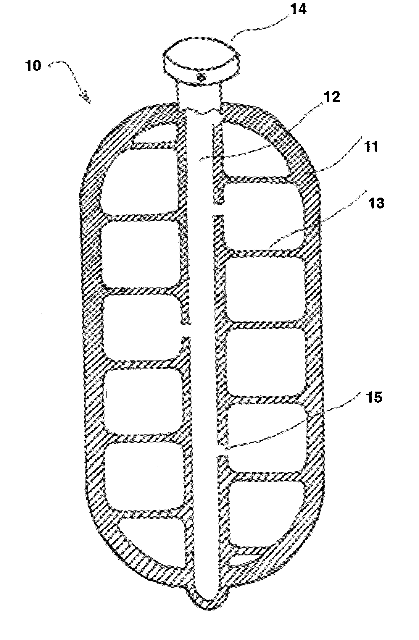
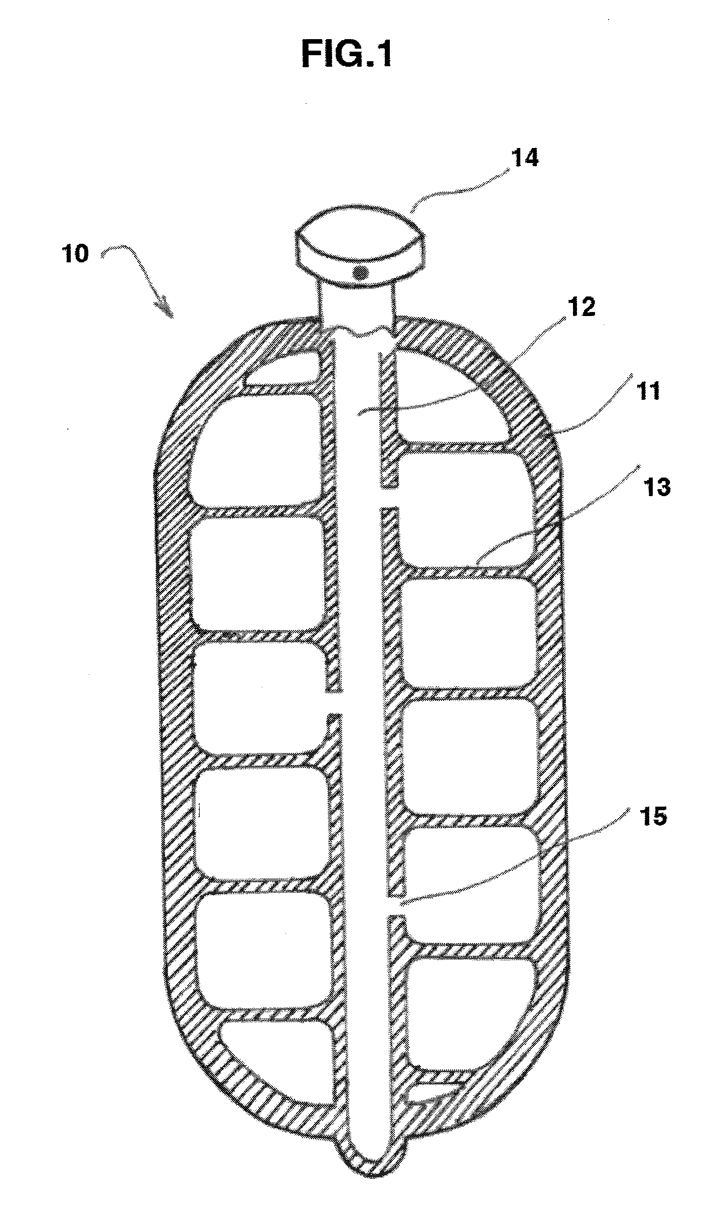
[0061]FIG. 1 shows a vertical cross-section of a first preferred embodiment 10 of the inventive pressure vessel. This embodiment comprises a generally cylindrical, hermetically sealed pressure vessel 10, having an external wall structure 11 and an internal supportive structure which includes a central supporting element 12 connected to wall 11 and bonds 13, which, in this embodiment, are in the form of spokes or traction rods. Bonds 13 perform an important function of transmitting the internal pressure forces applied to wall 11 to the central supporting element 12, which, in turn, transmits and distributes such pressure forces to the opposite side of the wall and vice versa. This allows vessel 10 to withhold much higher pressures as the same vessel made without such an internal supportive structure.

[0062]Bonds 13 can be distributed within vessel 10 either randomly or, in a preferred embodiment, using a configuration calculated to optimize force equalization within vessel 10. The emb...

embodiment 20

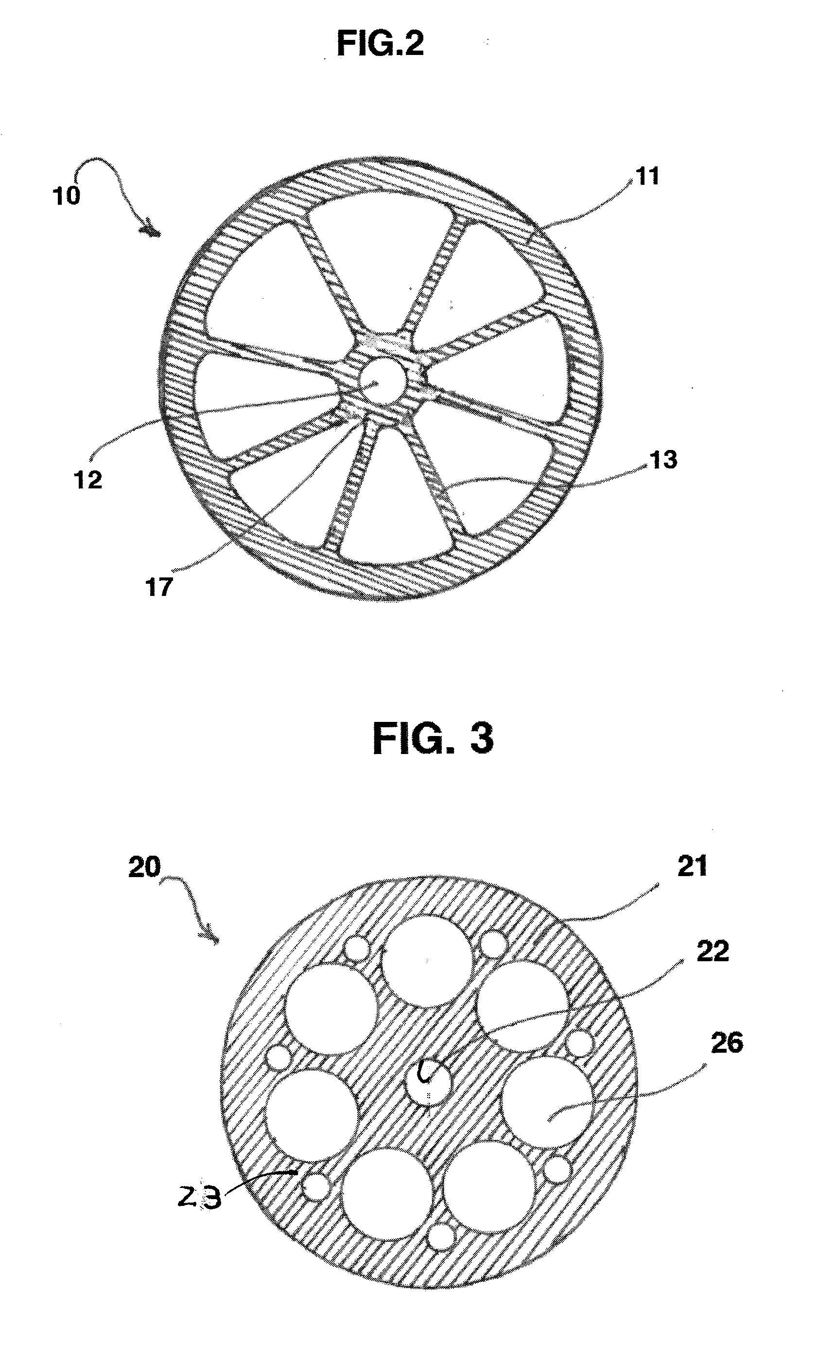
[0067]FIG. 4 shows the same embodiment 20 in a horizontal section. Here, we can better see wall 21, central supporting element 22, and disks 23, which play the role of bonds connecting central supporting element 22 with wall 21. Perforations 26 are omitted from FIG. 4 for ease of reference. A filling and release device, such as a valve 24 is situated on the top of vessel 20 communicating with central supporting element 22, which in turn, communicates with the interior of vessel 20 via holes 25.

[0068]FIG. 5 illustrates another embodiment of an internal supportive structure 30 of a vessel, this embodiment having a screw-like shape with one or more bonds 33 providing strong ties between the airtight walls of the vessel (not shown here) and a central supporting element 32, which is connected to the exterior environment with a filling and release device 34. Bonds 33 are perforated with openings 35 and are attached to a wall of the vessel forming one strong body capable of withstanding hi...


PUM

PropertyMeasurementUnit
pressuresaaaaaaaaaa
pressureaaaaaaaaaa
pressureaaaaaaaaaa

Abstract

Method and design of a pressure vessel having an internal supportive structure that reduces pressure forces applied to the external shell of the vessel by distributing such forces via internal bonds mostly connected to a central supporting element. The method and design allow making much lighter and stronger pressure vessels and containers using additive manufacturing technology, known as 3D printing.

Description

BACKGROUND OF THE INVENTION[0001]1. Field of the Invention[0002]This invention is in the field of pressure vessels such as those that are used in a variety of applications worldwide. These applications include industrial compressed air receivers, domestic hot water storage tanks, diving cylinders, recompression chambers, distillation towers, pressure reactors, autoclaves, and many other vessels in mining operations, oil refineries, petrochemical plants and nuclear reactor vessels.[0003]Other applications include submarine and space ship habitats, aircraft pressurized systems, pressurized pneumatic and hydraulic reservoirs, rail vehicle airbrake reservoirs, road vehicle airbrake reservoirs, and storage vessels for liquefied gases such as ammonia, chlorine, propane and butane, and modern vehicles using compressed gases for their engines.[0004]By way of only one (non-limiting example), fire suppression systems require high-pressure storage containers (also called bottles or cylinders),...

Claims


Application Information

Patent Timeline
Patent Type & Authority Applications(United States)
IPC IPC(8): F17C1/08B22F3/105B23K15/00B23K26/00B23K26/342B29C67/00F15D1/04F16L9/04F16L9/10F16L9/12F17C13/04
CPCB23K15/0086F17C2209/22F17C2260/01F17C2270/0142F17C2203/0663F17C2203/012F17C13/04F17C1/08F16L9/12F16L9/10F16L9/04F15D1/04B29L2031/7156B29K2995/0078B29K2101/12B29C67/0077B23K2203/14B23K2203/10B23K2203/08B23K26/0006B23K15/0093F16K31/30F17D1/12B23K2203/52F17C1/00F17D3/18F17C2201/054F17C2205/0323F17C2205/0326F17C2205/0335F17C2205/0352F17C2221/035F17C2223/0153F17C2223/033F17C2225/0123F17C2225/0153F17C2225/031F17C2225/033F17C2250/043F17C2250/0434F17C2250/0443F17C2250/0689F17C2250/0694F17C2250/072F17C2260/02F17C2260/038F17C2270/0102F17C2270/0165F17C2270/0168B23K2203/50B23K2203/42B23K2203/40B23K2203/30B23K2203/05B23K26/342B33Y80/00B33Y10/00B22F3/1055B22F5/10B29C70/32B29C64/153B29C64/40B23K2103/26B23K2103/05B23K2103/10B23K2103/14B23K2103/40B23K2103/42B23K2103/50B23K2103/52Y02P10/25B22F10/18B22F10/28B22F10/00Y02E60/34
Inventor KOTLIAR, IGOR, K.
Owner KOTLIAR IGOR K
Why Eureka
Try Eureka