Measurement system
a measurement system and measurement technology, applied in the field of measurement systems, can solve problems such as the adverse effect of reflection light detection
- Summary
- Abstract
- Description
- Claims
- Application Information
AI Technical Summary
Benefits of technology
Problems solved by technology
Method used
Image
Examples
first embodiment
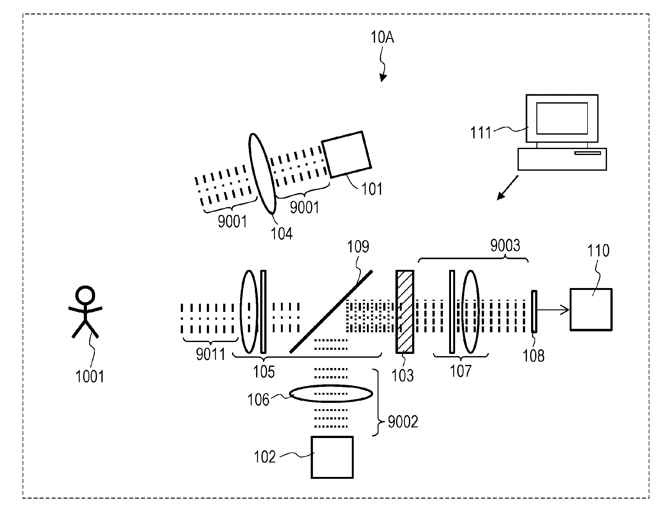
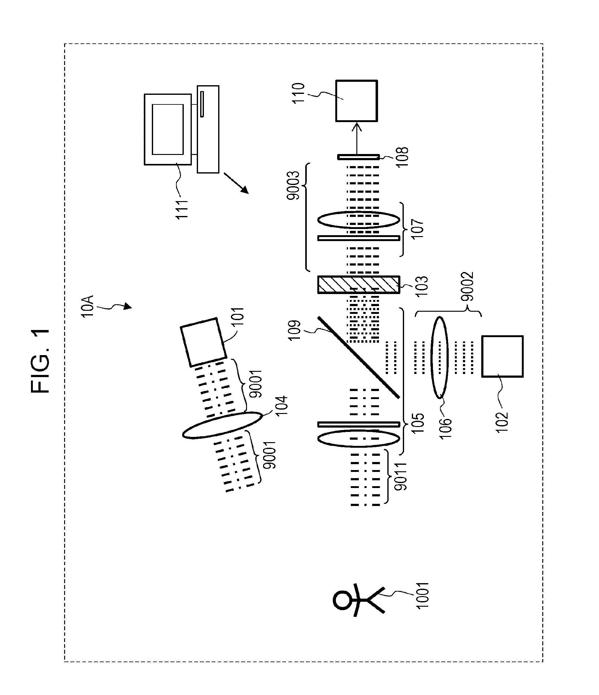
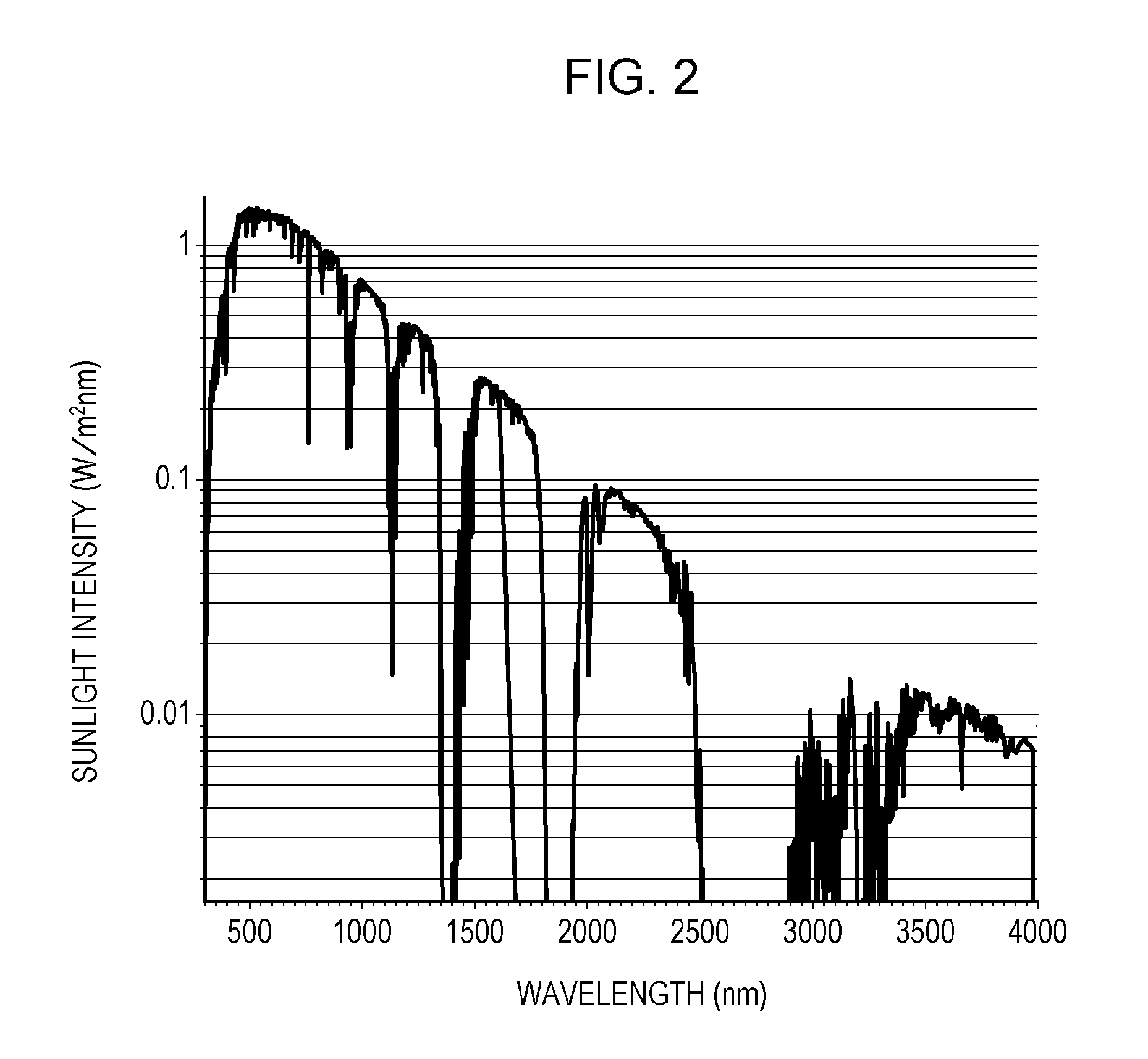
[0064]Hereinafter, the structure and the function of TOF image pickup system 10A will be described with reference to FIGS. 1 and 2.
[0065]FIG. 1 schematically illustrates the configuration of the TOF image pickup system 10A according to the present embodiment. It is to be noted that this configuration diagram illustrates only the elements necessary to describe the present disclosure. Also, the configuration diagram is strictly a diagram illustrating the concept. The shape, aspect ratio, and scale of each element in reality are not taken into consideration at all.
[0066]The TOF image pickup system 10A includes a first light source 101, a second light source 102, a nonlinear optical crystal 103, a first optical system 104, a second optical system 105, a third optical system 106, a fourth optical system 107, an image sensor 108, an optical mixing element 109, a processor 110, and a controller 111. A light source unit includes the first light source 101 and the second light source 102. Th...
second embodiment
[0129]A TOF image pickup system 10B that uses pulsed light as irradiation light will be described with reference to FIGS. 4 to 7D.
[0130]FIG. 4 schematically illustrates the configuration of the TOF image pickup system 10B according to the present embodiment. Hereinafter, different points from the first embodiment will be mainly described and detailed description of similar points is omitted.
[0131]The first light source 101 generates the first intensity-modulated light 9001. The first light 9001 is treated as a train of impulses with a narrow pulse width that are emitted with a certain period.
[0132]As described in the first embodiment, the wavelength of the first light 9001 may be selected freely. In the present embodiment, light with a wavelength of 1450 nm is utilized. The wavelength belongs to the sunlight lacking wavelength band and is an eye safe wavelength with which an image is not formed on the retina.
[0133]The object 1001 is irradiated with the first light 9001 using the fir...
third embodiment
[0164]An image pickup system 10C according to the present embodiment will be described with reference to FIGS. 9 to 12E. The image pickup system 10C has substantially the same configuration as that of the image pickup system 10A according to the first embodiment. In the present embodiment, efficient functioning of the image pickup system 10C in image pick-up in bad weather such as fog will be described.
[0165]FIG. 9 schematically illustrates the configuration of the image pickup system 10C according to the present embodiment. As illustrated, the object 1002 includes a fog 1041. The reflection light 9011 from the object 1002 includes reflection light 9311 from an object 1031 and reflection light 9411 from the fog. Hereinafter, it is assumed that the modulation of the second light 9002 is polarization modulation.
[0166]FIG. 10A illustrates the intensity of the first light 9001. FIG. 10B illustrates the intensity of the reflection light 9311 from the object. FIG. 10C illustrates the inte...
PUM
 Abstract
Description
Claims
Application Information
 - R&D
- Intellectual Property
- Life Sciences
- Materials
- Tech Scout
- Unparalleled Data Quality
- Higher Quality Content
- 60% Fewer Hallucinations
Browse by: Latest US Patents, China's latest patents, Technical Efficacy Thesaurus, Application Domain, Technology Topic, Popular Technical Reports.
© 2025 PatSnap. All rights reserved.Legal|Privacy policy|Modern Slavery Act Transparency Statement|Sitemap|About US| Contact US: help@patsnap.com


