Honeycomb filter

a filter and honeycomb technology, applied in the field of honeycomb filter, can solve the problems of insufficient filtration, insufficient filtration, insufficient filtration, etc., and achieve the effect of effectively preventing crack generation, reducing pressure loss, and efficient trapping and removing particulate matter

Active Publication Date: 2016-03-10
NGK INSULATORS LTD
View PDF2 Cites 15 Cited by
  • Summary
  • Abstract
  • Description
  • Claims
  • Application Information

AI Technical Summary

Benefits of technology

[0029]The honeycomb filter of the present invention is capable of efficiently trapping and removing particulate matter included in an exhaust gas emitted from a direct injection type gasoline engine or a diesel engine, and reducing pressure loss in an initial stage as well as during PM deposition. Additionally, the honeycomb filter of the present invention is capable of effectively preventing generation of cracks due to concentration of thermal stress during PM burning, and the like. In addition, heat during the PM burning is easily propagated among a plurality of inflow side cells (outlet plugged cells) and hence, regeneration of the honeycomb filter can efficiently be performed. Furthermore, the honeycomb filter of the present invention has less plugging portions on an inflow end face side, and hence, a heat capacity on the inflow end face side of the honeycomb filter becomes smaller, ignitability during the PM burning improves, and continuous regeneration properties by NO2 improve.

Problems solved by technology

However, heightening of an open frontal area of inflow side cells (outlet plugged cells) relatively results in decrease of an open frontal area of outflow side cells (inlet plugged cells), and hence, there has been the problem that, with this decrease, a pressure loss in an initial stage (the initial pressure loss) disadvantageously heightens.
In consequence, there has been the problem that temperature rise on the inflow end face side due to an exhaust gas becomes dull and continuous regeneration properties due to NO2 worsen.
In addition, when inflow side cells (the outlet plugged cells) differs from the outflow side cells (the inlet plugged cells) in a sectional area and a sectional shape, a thickness of partition walls forming the cells becomes smaller in a part of a portion in which the partition walls intersect each other (hereinafter referred to as “the intersecting portion” sometimes) in a certain case, and there has been the problem that strength deteriorates.
Consequently, there has been the problem that, when PM deposited on the DPF is burnt and removed by post injection, thermal stress is concentrated on a part of the thinned intersecting portion, and breakage such as generation of cracks is easily caused.
However, in this structure of the honeycomb filter described in Patent Document 3, there has been the problem that, when the plurality of inflow side cells (the outlet plugged cells) are arranged discontinuously from one another, heat during the burning and removal of the PM is hard to be propagated to the adjacent inflow side cell (the outlet plugged cell), and the honeycomb filter cannot efficiently be regenerated.

Method used


Image

  • Honeycomb filter
  • Honeycomb filter
  • Honeycomb filter

Examples


example 1

[0064]As a ceramic raw material, a mixture of silicon carbide (SiC) powder and metal silicon (Si) powder at a mass ratio of 80:20 was prepared. To this ceramic raw material, hydroxypropoxyl methylcellulose as a binder and a water absorbable resin as a pore former were added, and water was also added, to prepare a forming raw material. The obtained forming raw material was kneaded by using a kneader, to obtain a kneaded material.

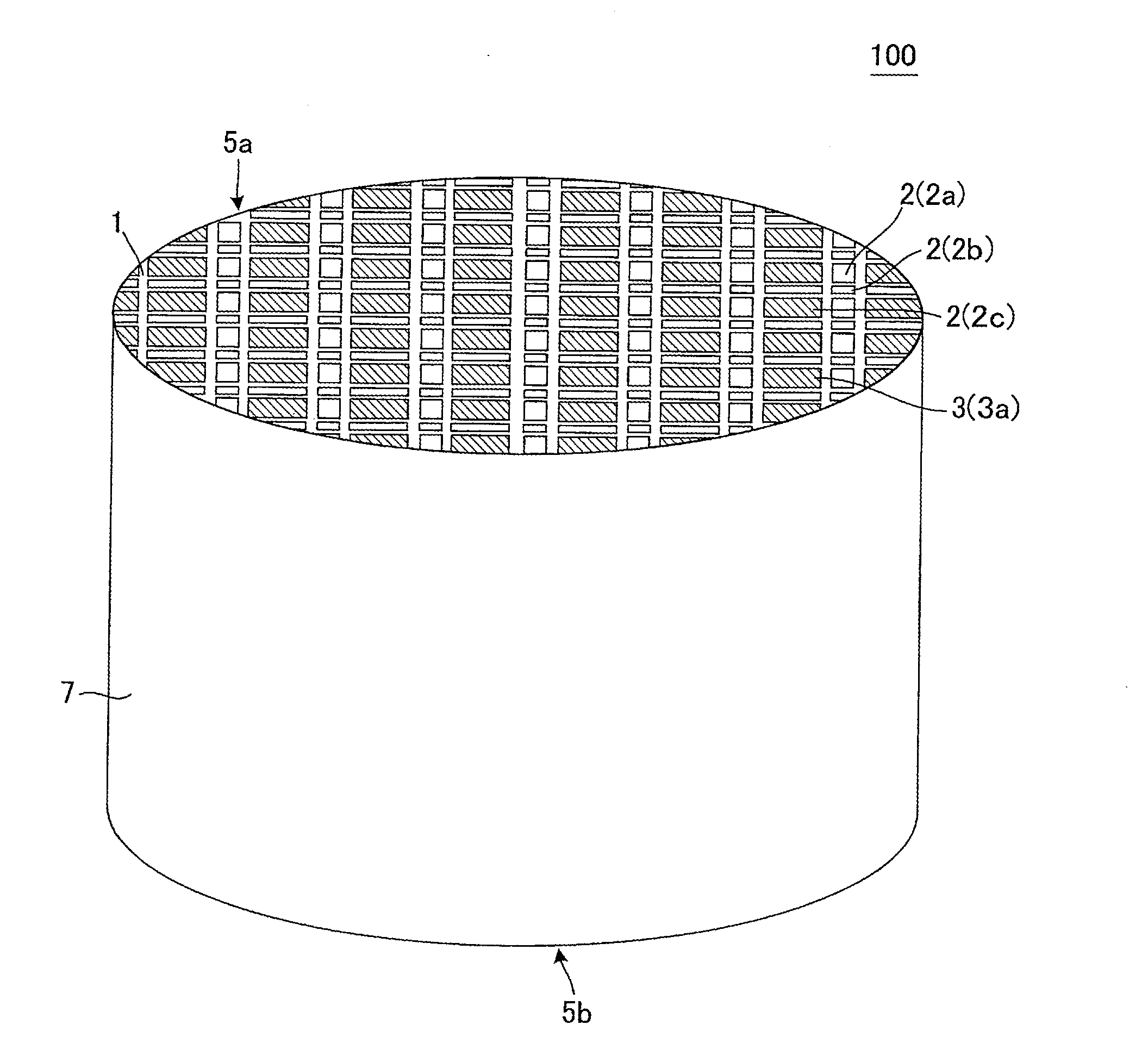
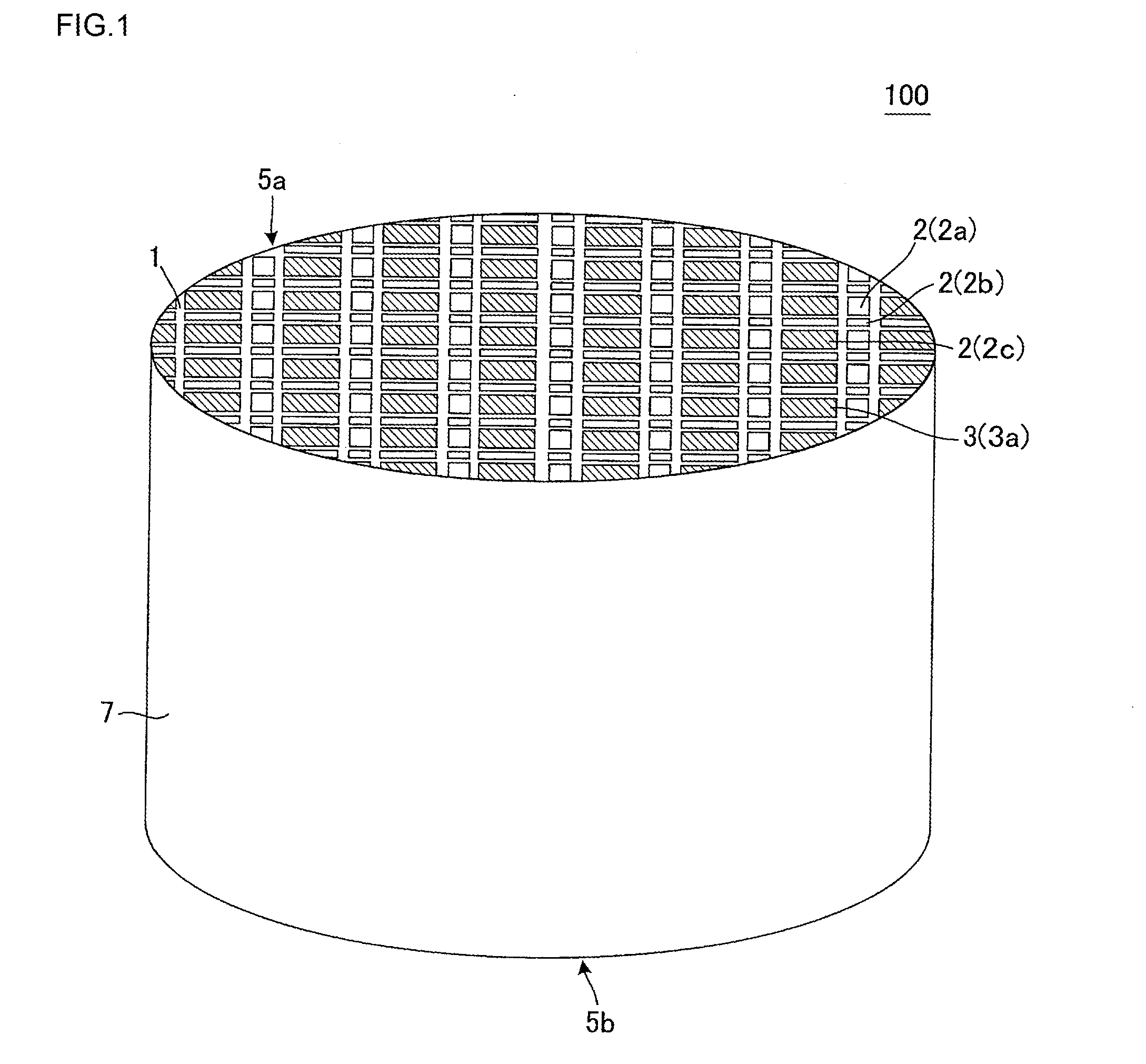
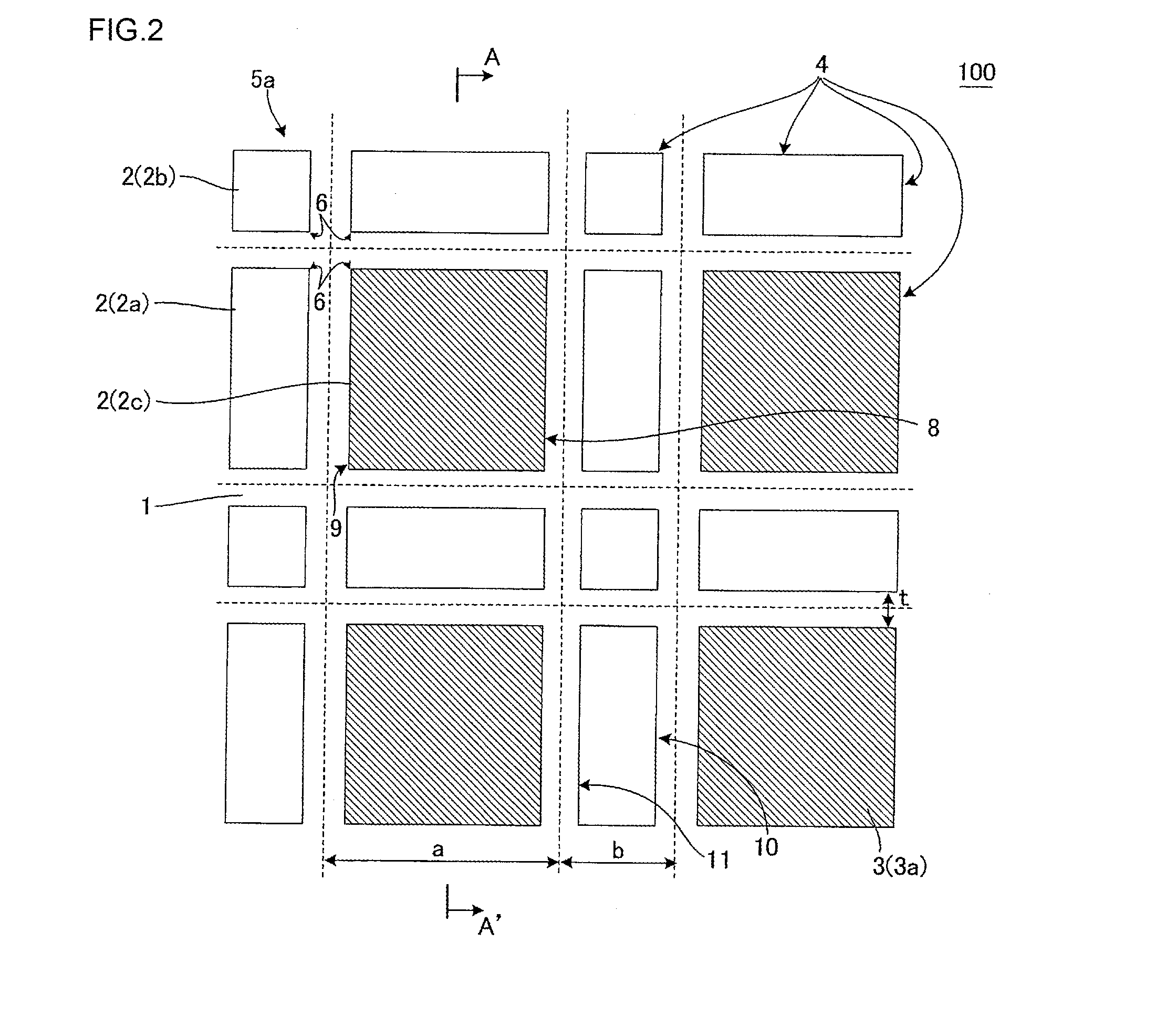
[0065]Next, the obtained kneaded material was formed by using a vacuum extruder and 16 rectangular pillar-shaped honeycomb segments each having such a plugging arrangement as shown in FIG. 2 and FIG. 3 were prepared. A sectional shape of each honeycomb segment in a direction perpendicular to a cell extending direction was a square of 36 mm×36 mm and the segment had a length of 152 mm. In addition, a partition wall center distance a shown in FIG. 2 was set to 2.2 mm, a partition wall center distance b was set to 0.76 mm and a partition wall thickness t was 0.3...


PUM

PropertyMeasurementUnit
center distanceaaaaaaaaaa
thicknessaaaaaaaaaa

Abstract

The honeycomb filter includes a honeycomb substrate having porous partition walls defining a plurality of cells and plugging portions. In a cross section, the cells are arranged so that a periphery of an inlet plugged cell including an open end whose shape is a square in which a length of one side is L1 is surrounded with four rectangular outlet plugged cells each including an open end whose shape is a rectangle in which a length of one side is L1 and a length of the other side is L2 (L1>L2) and four square outlet plugged cells each including an open end whose shape is a square in which a length of one side is L2. A partition wall center distance a, a partition wall center distance b and a partition wall thickness t satisfy the following equation (1):
0.95<b/at<1.90  (1).

Description

[0001]The present application is an application based on JP 2014-180013 filed on Sep. 4, 2014 with Japan Patent Office, the entire contents of which are incorporated herein by reference.BACKGROUND OF THE INVENTION[0002]1. Field of the Invention[0003]The present invention relates to a honeycomb filter. More particularly, it relates to a honeycomb filter to be suitably used in purification of particulate matter included in an exhaust gas from an engine, especially a car engine, and toxic gas components such as nitrogen oxides (NOx), carbon monoxide (CO) and hydrocarbons (HC).[0004]2. Description of the Related Art[0005]In recent years, reductions of fuel consumptions of cars have been required from the viewpoints of influences on the global environment and resource saving. Consequently, there is the tendency that internal combustion engines such a direct injection type gasoline engine and a diesel engine each having an excellent thermal efficiency are used as power sources for the car...

Claims


Application Information

Patent Timeline
Patent Type & Authority Applications(United States)
IPC IPC(8): F02M35/024B01D46/24
CPCF02M35/02475B01D46/2418B01D2046/2433B01D46/2425B01D46/2429F01N3/0222B01D46/247B01D46/2474Y02T10/12B01D46/24491B01D46/2484B01D46/2482B01D46/249
Inventor MIYAIRI, YUKIOKUMAZAWA, KAZUHIKOHIRAKAWA, TOSHIHIROYAMADA, TOSHIO
Owner NGK INSULATORS LTD
Why Eureka
Try Eureka